 |
|||
|
|
|||
|
Page Title:
FRONT AND REAR WINDSHIELD WIPERS DO NOT OPERATE - continued |
|
||
| ||||||||||
|
|
 TM 10-3930-673-20-1
P2-1
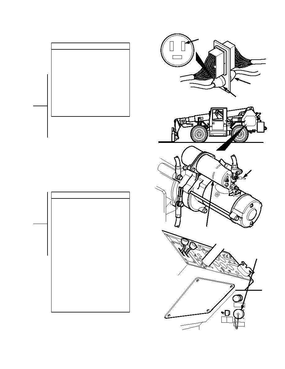
CONTINUITY TEST
(1) Disconnect negative battery cable from
negative side of battery (Para 8-44).
(2) Disconnect connector J2 from
connector P2.
CONNECTOR P2
(3) Set multimeter to ohms.
(4) Connect multimeter positive lead (+) to
wire 9 where wire 9 connects to starter
motor solenoid.
CONNECTOR
J
(5) Connect multimeter negative lead () to
2
connector P2-1.
CONNECTOR P2
(a) If continuity is present, go to Step 4
of this fault.
(b) If continuity is not present, repair
wire 9 or connector P2 (Para 8-49).
WIRE 9
VOLTAGE TEST
(1) Connect negative battery cable to
negative side of battery.
(2) Remove dust cover from DCA-1
connector.
(3) Connect cable W1 to the Vehicle Test
Meter (VTM) and DCA-1 connector.
STARTER SOLENOID
(4) Power up STE/ICE-R VTM in the DCA
mode (TM 9-4910-571-12&P).
(5) Turn auxiliary fuel shut-off switch on.
(6) Start engine (TM 10-3930-763-10).
C
DCA-1
(7) Perform STE/ICE test #82.
(8) Press and release test button.
ONNECTOR
(9) Observe VTM display for test results.
(a) If voltage is present at output of
alternator, go to Step 4 of this fault.
(b) If voltage is not present at output of
alternator, replace alternator
(Para 8-2).
(10) Shut off engine (TM 10-3930-673-10).
(11) Turn auxiliary fuel shut-off switch off.
(12) Power down STE/ICE-R VTM in the
DCA mode (TM 9-4910-571-12&P).
(13) Disconnect DCA cable from DCA-1(2).
(14) Install battery cover (Para 8-42).
TR01164
2-435
|
|
Privacy Statement - Press Release - Copyright Information. - Contact Us |