 |
|||
|
|
|||
|
Page Title:
BLACKOUT STOPLIGHTS DO NOT OPERATE - continued |
|
||
| ||||||||||
|
|
 TM 10-3930-673-20-1
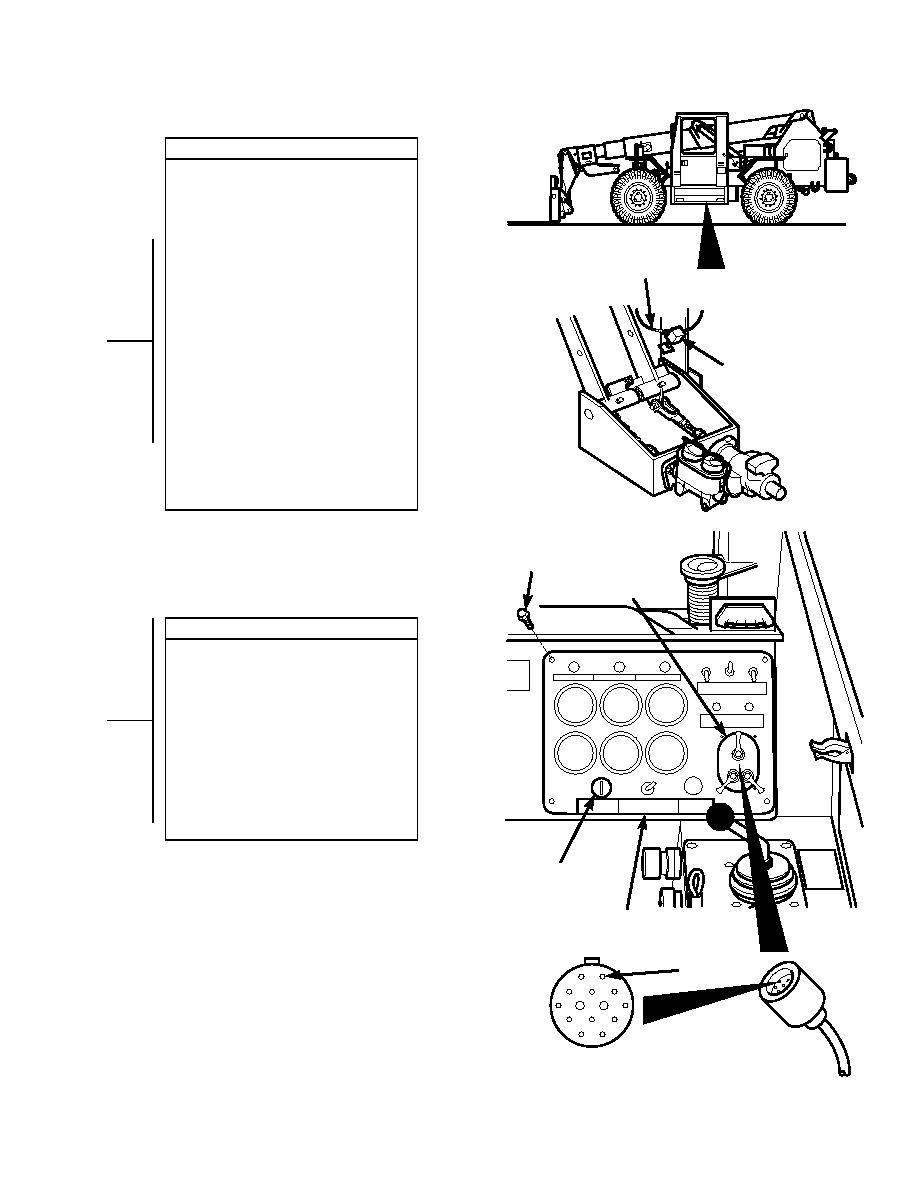
VOLTAGE TEST
(1) Set multimeter to volts dc.
(2) Connect multimeter positive lead (+) to
brake light switch where wire 41
connects.
(3) Connect multimeter negative lead () to
known good ground.
W4RE
I
(4) Connect negative battery cable to
1
negative side of battery (Para 8-42).
(5) Turn engine start switch to ON position,
BUT DO NOT START ENGINE
(TM 10-3930-673-10).
(6) Turn blackout light switch to B. O.
DRIVE position (TM 10-3930-673-10).
BRAKE
L
(a) If 24 vdc is present, go to Step 13
S IGHT
of this fault.
(b) If 24 vdc is not present, go to
WITCH
Step 12 of this fault.
(7) Turn blackout light switch to OFF
position (TM 10-3930-673-10).
(8) Turn engine start switch to OFF
position, (TM 10-3930-673-10).
(9) Disconnect negative battery cable from
negative side of battery (Para 8-42).
SCREW
L BLACKOUT
IGHT SWITCH
CONTINUITY TEST
(1) Lift instrument panel out to remove
connector J3 from blackout light switch.
(2) Set multimeter to ohms.
(3) Connect multimeter positive lead (+) to
connector J3-A (wire 41).
(4) Connect multimeter negative lead () to
brake switch where wire 41 connects.
(a) If continuity is present, replace
blackout light switch (Para 8-13).
(b) If continuity is not present, repair
wire 41 (Para 8-48).
(5) Connect connector J3 to blackout light
switch.
ENGINE START
S
WITCH
INSPRUMENT
T
ANEL
J3-A
CONNECTOR J3
TR01647
2-357
|
|
Privacy Statement - Press Release - Copyright Information. - Contact Us |
