 |
|||
|
|
|||
|
Page Title:
BLACKOUT DRIVE LIGHT(S) DO NOT OPERATE - continued |
|
||
| ||||||||||
|
|
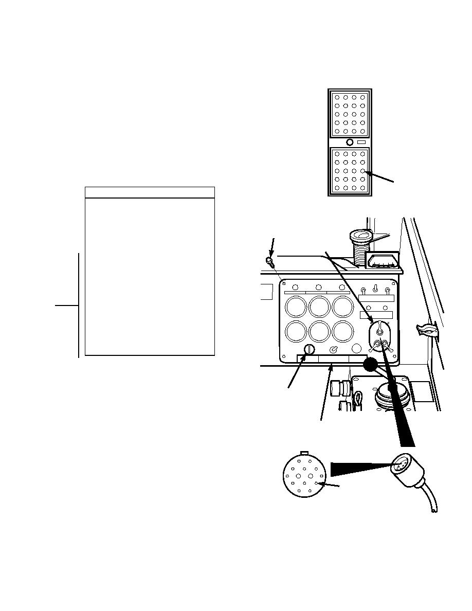 TM 10-3930-673-20-1
J1-3
CONTINUITY TEST
CONNECTOR J1
(1) Remove four screws from instrument
panel.
(2) Lift instrument panel out to remove
connector J3 from blackout light switch.
SCREW
(3) Disconnect connector J1 from
BLACKOUT
connector P1.
LIGHT SWITCH
(4) Set multimeter to ohms.
(5) Connect multimeter positive lead (+) to
connector J3-D (wire 47).
(6) Connect multimeter negative lead () to
connector J1-3 (wire 47).
(a) If continuity is present, replace
blackout light switch (Para 8-13).
(b) If continuity is not present, repair
wire 47 (Para 8-48).
(7) Lift instrument panel out to connect
connector J3 to blackout light switch.
(8) Connect connector J1 to connector P1.
(9) Install four screws to secure instrument
panel.
ENGINE START
SWITCH
INSTRUMENT
PANEL
J3-D
CONNECTOR J3
TR01670
2-337
|
|
Privacy Statement - Press Release - Copyright Information. - Contact Us |
