 |
|||
|
|
|||
|
Page Title:
BLACKOUT MARKER LIGHT(S) AND/OR TAILLIGHT(S) DO NOT OPERATE - continued |
|
||
| ||||||||||
|
|
 TM 10-3930-673-20-1
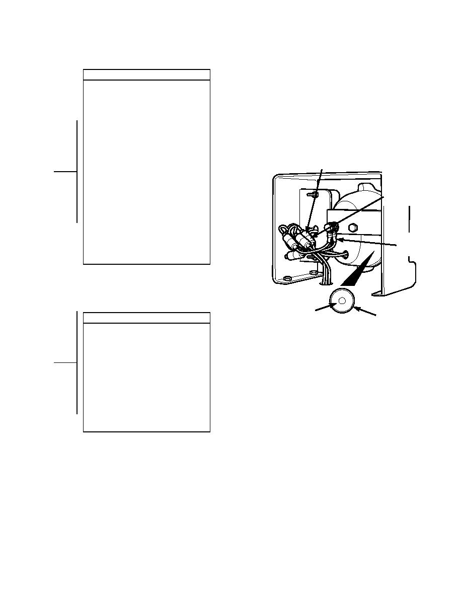
VOLTAGE TEST
(1) Set multimeter to volts dc.
(2) Connect multimeter positive lead (+) to
tail light female connector where
wire 45 connects.
(3) Connect multimeter negative lead () to
known good ground.
(4) Connect negative battery cable to
negative side of battery (Para 8-42).
(5) Turn engine start switch to ON position,
C
MALE
BUT DO NOT START ENGINE
(TM 10-3930-673-10).
ONNECTOR
(6) Turn blackout light switch to B. O.
MARKER position
FEMALE
C
(TM 10-3930-673-10).
ONNECTOR
(a) If 24 vdc is present, go to Step 14
of this fault.
(b) If 24 vdc is not present, repair
wire 45 (Para 8-48).
(7) Turn blackout light switch to OFF
position (TM 10-3930-673-10).
(8) Turn engine start switch to OFF
GROUND
position, (TM 10-3930-673-10).
(9) Disconnect negative battery cable from
negative side of battery (Para 8-42).
S
TAILLIGHT
OUTSIDE
C
CONTINUITY TEST
OCKET
ONDUCTOR
(1) Disconnect ground female connector
TR01702
from male ground connector.
(2) Set multimeter to ohms.
(3) Connect multimeter positive lead (+) to
ground outside conductor at taillight
socket.
(4) Connect multimeter negative lead () to
ground cable.
(a) If continuity is present, replace
bulb (Para 8-33).
(b) If continuity is not present, repair
wire 2 (Para 8-49) or replace
blackout tail or marker light socket
(Para 8-33).
2-319
|
|
Privacy Statement - Press Release - Copyright Information. - Contact Us |
