 |
|||
|
|
|||
|
Page Title:
REAR FLOODLIGHT DOES NOT OPERATE - continued |
|
||
| ||||||||||
|
|
 TM 10-3930-673-20-1
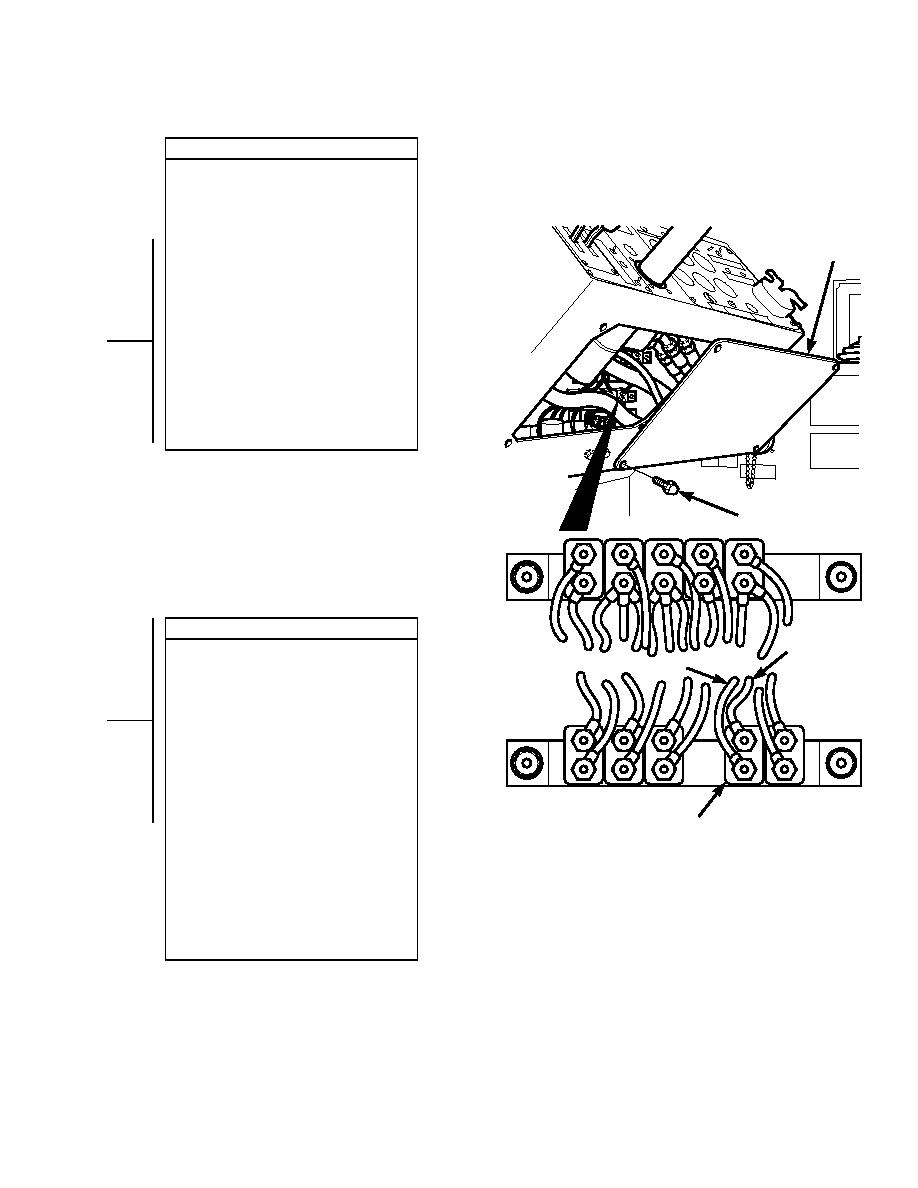
VOLTAGE TEST
(1) Set multimeter to volts dc.
(2) Connect multimeter positive lead (+) to
circuit breaker CB7 where wire 5
connects.
(3) Connect multimeter negative lead () to
ACCESS
P
known good ground.
ANEL
(4) Connect negative battery cable to
negative side of battery (Para 8-42).
(5) Turn engine start switch to ON position,
BUT DO NOT START ENGINE
(TM 10-3930-673-10).
(a) If 24 vdc is present, go to Step 13
of this fault.
(b) If 24 vdc is not present, repair
wire 5 (Para 8-48).
(6) Turn engine start switch to OFF
position (TM 10-3930-673-10).
(7) Disconnect negative battery cable from
negative side of battery (Para 8-42).
SCREW
VOLTAGE TEST
WIRE 70
(1) Set multimeter to volts dc.
WIRE 5
(2) Connect multimeter positive lead (+) to
circuit breaker CB7 where wire 70
connects.
(3) Connect multimeter negative lead () to
known good ground.
(4) Connect negative battery cable to
negative side of battery (Para 8-42).
(5) Turn engine start switch to ON position,
BUT DO NOT START ENGINE
(TM 10-3930-673-10).
(a) If 24 vdc is present, go to Step 14
CIRCUIT BREAKER CB7
of this fault.
(b) If 24 vdc is not present, replace
TR01573
circuit breaker CB7 (Para 8-11).
(6) Turn engine start switch to OFF
position (TM 10-3930-673-10).
(7) Disconnect negative battery cable from
negative side of battery (Para 8-42).
(8) Install access panel and four screws to
secure access panel.
2-299
|
|
Privacy Statement - Press Release - Copyright Information. - Contact Us |
