 |
|||
|
|
|||
|
Page Title:
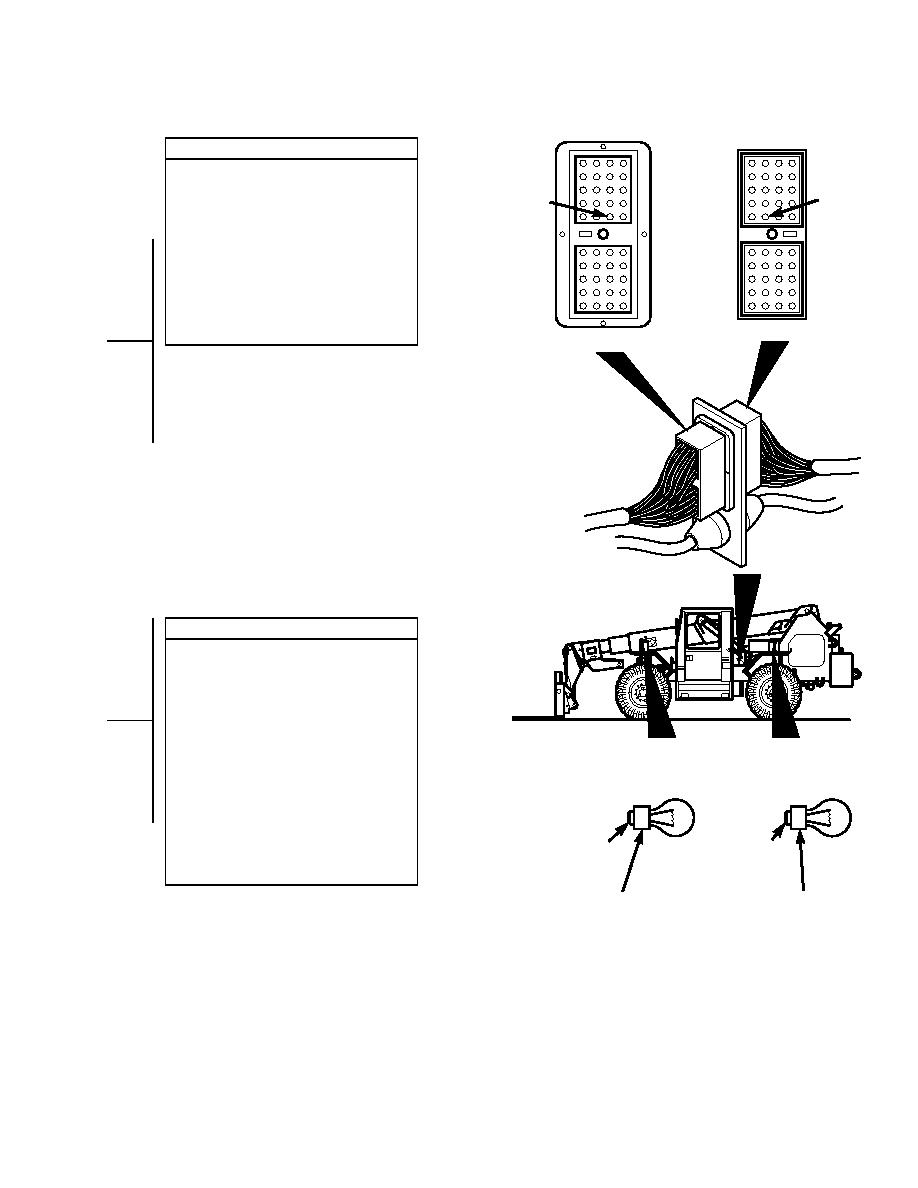
RIGHT TURN SIGNAL DOES NOT OPERATE - continued |
|
||
| ||||||||||
|
|
 TM 10-3930-673-20-1
CONTINUITY TEST
(1) Set multimeter to ohms.
(2) Disconnect connector J1 from
J1-26
P1-26
connector P1.
(3) Connect multimeter positive lead (+) to
turn signal switch wire 28.
(4) Connect multimeter negative lead () to
connector J1-26.
(a) If continuity is present, go to Step 7
of this fault.
(b) If continuity is not present, repair
connector J1 or wire 28
CONNECTOR J1
(Para 8-48).
CONNECTOR P1
CONTINUITY TEST
(1) Set multimeter to ohms.
(2) Connect multimeter positive lead (+) to
turn signal socket center conductor.
(3) Connect multimeter negative lead () to
connector P1-26.
(a) If continuity is present, replace
bulb (Para 8-33).
SREAR TURN
S
FRONT TURN
(b) If continuity is not present, repair
IGNAL BULB
IGNAL BULB
connector P1 or wire 28
(Para 8-49).
(4) Connect connector J1 to connector P1.
(5) Install four screws to secure access
panel.
C
CENTER
(6) Connect negative battery cable to
C
CENTER
negative side of battery (Para 8-42).
ONDUCTOR
ONDUCTOR
(7) Install battery cover (Para 8-42).
C OUTSIDE
C OUTSIDE
ONDUCTOR
G
ONDUCTOR
G
ROUND
ROUND
TR01716
2-227
|
|
Privacy Statement - Press Release - Copyright Information. - Contact Us |
