| |
TM 10-3930-671-24
ASSEMBLE STATOR TO REAR HOUSING - Place
stator in rear housing, with leads extended toward heat
sink. Assemble diode and stator leads to diode terminal
screws. When properly assembled, each screw will hold
a black lead from a negative diode, a red lead from a
positive diode and a lead from the stator. The terminal
screw nearest to the stator terminal, will also hold the
stator tap lead wire.
Install washers and nuts, secure. Arrange all leads to
prevent accidental contact with surfaces or through bolts.
Align stator slots with through bolt holes.
ASSEMBLE FRONT AND REAR HOUSING - Place
front housing, with rotor assembled, in a vise, drive end
down. Place sealing gasket over top edge of-front
housing. Place rear housing and heat sink assembly
over top end of rotor, align bearing cavity and press
halves together.
Position gasket to align with through bolts. Install bolts
and tighten securely. Spin rotor by hand to insure proper
assembly.
INSTALL BRUSH ASSEMBLY AND COVER - Place
insulator over brush assembly, slide into brush cavity,
position with alignment pins. Secure insulator and brush
assembly to rear housing with screws. Connect brush
lead to cover. Place gasket in recess area, install brush
cover, secure with screws.
INSTALL PULLEY AND FAN - Place pulley soacer over
rotor shaft, install Woodruff key in slot. Place fan and
pulley on shaft and install lockwasher and nut. Secure
nut at 35 to 50 ft. lbs. Spin rotor by hand to insure fan
does not rub housing. This completes the assembly of
the alternator.
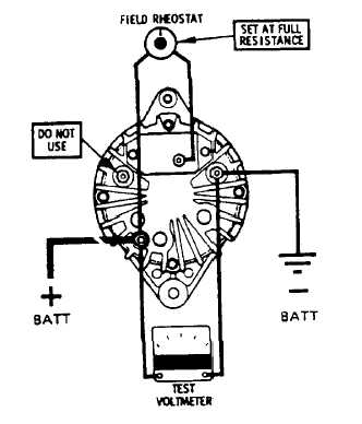
ALTERNATOR OPERATING TEST
(LESS REGULATOR) -
Mount alternator in test fixture capable of providing 3000
to 4000 alternator RPM, in either direction. Connect
circuit leads as shown in (Figure No. 65).
Turn drive motor on, adjust to obtain 3000 to 4000
alternator rotor speed. Reduce resistance of field
rheostat to zero. Alternator should commence to charge
and
reach
rated
output
in
amperes,
within
the
recommended speed range. Obtaining rated output,
alternator is suitable for installation.
Do not operate alternator for more than a few minutes in
this manner, due to the lack of voltage control.
FIGURE NO. 65.
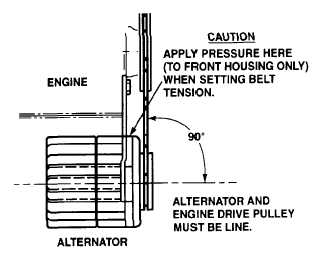
When reinstalling alternator on engine, accurately align
alternator and engine drive pulley (Figure No. 66).
FIGURE NO. 66.
To tighten belt, press against front housing, near
alternator fan. Do not apply pressure to alternator rear
housing.
Set
belt
tension
per
manufacturer’s
recommended specifications and tighten all bolts. If
manufacturer’s specifications are not readily available,
set belt tension tight enough so that the belt on alternator
fan pulley will not slip when attempting to rotate
alternator fan by hand.
F-296
|