| |
TM 10-3930-671-24
FIGURE NO. 41.
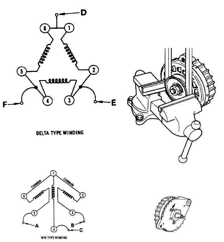
The Wye circuit used in 22 ampere TA alternators,
provides a common winding termination, plus three leads
to connect the stator to the rectifying diodes (A - B - C)
(Figure No. 42).
FIGURE NO. 42.
PULLEY REMOVAL - The various pulleys applicable to
the TA alternator, are of a slip type fit. A Woodruff key is
incorporated on the rotor shaft for "keying" of the pulley
and fan. To remove the nut and lockwasher, clamp
the pulley in a vise, using an old oversized belt to protect
the pulley from damage by the vise jaws (Figure No.
43).After pulley mounting nut, and split lock-washer have
been removed, the alternator should "pull" back and
away from pulley.
NOTE
Should pulley be "frozen" to rotor
shaft, while supporting alternator,
strike end of shaft with a wooden
mallet, plastic hammer or a special
puller to break pulley free from shaft.
FIGURE NO. 43.
ROTOR REMOVAL FROM FRONT HOUSING -
1.
Remove three 8-32 Phillips head, machine
screws and lockwashers from the front housing
(Figure No. 44).
FIGURE NO. 44.
F-291
|