| |
TM 10-3930-671-24
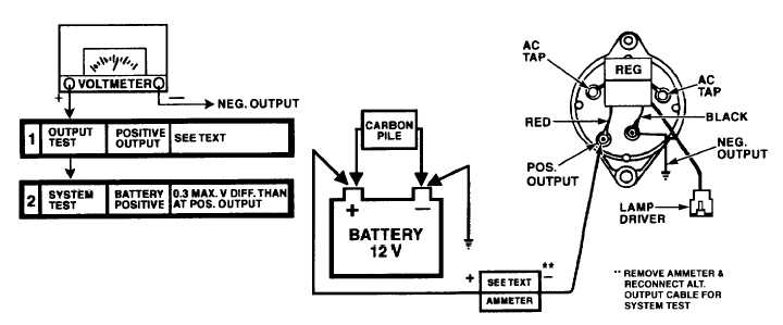
FIGURE NO. 17.1.
ALTERNATOR OUTPUT AND SYSTEM TEST (45 Amp Systems) - This test will determine if the alternator is capable of
producing a minimum rated output. Position load control knob of carbon pile to the "OFF" position prior to connecting
leads to battery terminals. The test requires that a test ammeter be set to the 0-200 ampere scale, and connected in
series with the alternator positive output terminal and battery positive terminal, as shown in Figure No. 17.1.
Start the engine and allow it to run for a few minutes to stabilize component temperatures. Adjust engine speed to 3000-
5000 alternator rpm. Apply carbon pile load to the battery to induce highest alternator current output.
Note voltage output. Minimum acceptable (hot) alternator output should be 41-45 amperes. Output voltage must remain
between 13.0 and 15.0 volts.
If alternator cannot produce the required output, remove from engine and rebuilt. Reduce carbon pile load on battery
immediately after testing to avoid discharging battery.
System voltage drop, between the alternator and the battery, is tested with the alternator producing 10 amperes. The
maximum allowable voltage drop, between alternator and battery is .3 (three tenths) volt. Excess voltage loss may require
cleaning and tightening of all circuit connections or replacement of output cables between the alternator and the battery.
ALTERNATOR
DISASSEMBLY
&
COMPONENT
TESTS
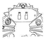
BRUSH ASSEMBLY REMOVAL
1.
Remove regulator to gain access to the brush
assembly cover (Figure No. 18).
FIGURE NO. 18.
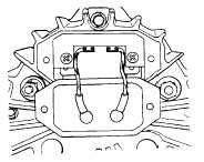
2 With brush assembly cover pulled down and away
from back housing, remove two 8 X 1/2" tapping
screws retaining brush assembly to housing
(Figure No. 19).
FIGURE NO. 19.
F-285
|