| |
TM 10-3930-671-24
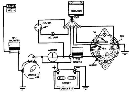
FIGURE NO. 17.
TABLE 2.
ALTERNATOR OUTPUT AND SYSTEM TEST - This test will determine if the alternator is capable of producing a
minimum rated output. The charging circuit is also tested under partial load to determine if there is excessive voltage loss
between the alternator and battery. The test ammeter remains connected in series with alternator output to battery.
Carbon pile, with load control knob turned off, is connected across the battery. Connect voltmeter, negative lead to
alternator ground terminal, positive lead to alternator output terminal (Figure No. 17).
Start engine and run at 700 to 1000 rpm. Slowly apply carbon pile load until alternator produces 10 ampere output. Let
engine operate in this manner for 5 minutes to stabilize component temperature. Increase engine speed to provide 3000
to 4000 alternator rpm. Repair punctured insulation with tape. Regulator may require replacement, if circuit inspection
fails to locate difficulty. A low voltage reading would indicate a defective voltage regulator. Remove or switch out 1/4 ohm
resistor immediately after test. Reconnect output lead to alternator output terminal.
Increase carbon pile load on the battery so alternator will develop its’ minimum rated output, indicated in Table No. 2.
Voltage must remain between 13.0 - 15.0 volts. If minimum rated output cannot be reached, the alternator will require
disassembly and repairs.
System voltage loss, due to loose connections, etc., is determined while the alternator is producing 10 ampere
output. The voltage measured across the battery should be within 0.3 volts of voltage measured from the alterna-
tor output and ground terminals. Turn carbon pile control knob off after test to avoid discharging battery.
Make necessary repairs to insulated or ground circuit to correct any deficiency.
F-284
|


