| |
TM 10-3930-671-24
observing the area to the left of the zero line or the
reverse bias area, it can be seen that until the 10V point
is reached, the Zener diode again acts electrically similar
to a normal diode, in the reverse bias direction it will not
allow current to flow. The instant the voltage rises above
10 volts the Zener diode "breaks down", allowing current
to flow. The ability of the Zener diode to "break down",
arid then heal itself as the voltage swings above and
below the avalanche point of the Zener diode is utilized
to switch the associated components in the regulator
"on" and "off, switching the field current won" and "off,
which
in
turn
holds
the
system
voltage
to
a
predetermined value.
THERMISTOR - Thermistor (RT) is a temperature
sensitive resistor, in the regulator voltage divider
network, designed to provide a varying resistance with
changes in regulator temperature. With the thermistor,
the charging voltage is automatically in- creased slightly
to overcome the tendency of a cold battery and
electrolyte to resist the charging force. The thermistor will
decrease charging voltage at higher temperatures as the
warm battery and electrolyte will accept the charging
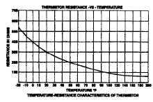
force at a lower charging voltage. A typical temperature-
resistance characteristic curve is shown in Figure No.7.
FIGURE NO. 7
With the above information understood, the operation
of the voltage regulator system will be easy to follow.
(Figure No. 8).
FIGURE NO. 8
SYSTEM VOLTAGE - When the voltage system rises
above a set value, the Zener diode (ZI) permits current to
flow in the base of the driver transistor (Q1). This
causes transistor 01 to turn "on" and reverse bias output
transistor 02, this in turn will turn "of’ the current applied
to the alternator field. The instant the system voltage
drops below the predetermined value, the Zener diode
stops conducting. When the Zener diode stops
conduction, forward bias is removed from the driver
transistor 01 and it stops conducting. This in turn allows
Q2 to begin conduction, allowing field current to be
applied to the altemator. As can be seen, the on-off
effect of output transistor 02 is essentially that of a switch
allowing alternator field current to be turned "on" and "off,
to maintain a specific voltage.
BATTERY INSTALLATION & CHARGING
PRECAUTIONS
CAUTION
Observe
proper
polarity
when
installing battery. Ground polarity of
battery
and
ground
polarity
of
altemator,
must
be
the
same.
Reverse polarity will destroy the
rectifier diodes in altemator. As a
precautionary measure, disconnect
positive (HOT) battery terminal when
charging
battery
In
vehicle.
Connecting charger in reverse will
destroy the rectifier diodes in the
altemator.
TEST
PRECAUTIONS
-
DO
NOT,
under
any
circumstances, short the field terminal of the altemator to
ground, as permanent damage to the regulator may
occur.
DO NOT, disconnect the voltage regulator while the
altemator is operating, because of the large transient
spike that occurs when disconnection takes place.
permanent damage to the regulator will occur.
F-274
|


