| |
TM 10-3930-671-24
Alternator Maintenance Precautions
WARNING
•
Disconnect
the
battery,
before
connecting
or
disconnecting
test
instruments
(except
voltmeter)
or
before removing or replacing any unit
or wiring. Accidental grounding or
shorting at the regulator, alternator,
ammeter or accessories, will cause
severe damage to the units and/or
wiring and possible injury to personnel.
•
If a booster battery or a fast charger is
used, its polarity must be connected
correctly to prevent damage to the
electrical
system
components.
Connect positive to positive, negative
to negative. Connect the negative
cable ground connection last (but not
to the battery because an explosion
could result).
CAUTION
•
The field circuit must never be
grounded on this system, between the
alternator
and
the
regulator.
Grounding of the field terminal either at
the alternator or regulator will damage
the regulator.
•
Do not ground the output terminal.
Grounding of the alternator output
terminal may damage the alternator
and/or circuit and components.
•
Do not connect battery to the regulator
field terminal or damage to the
regulator will result.
•
Do
not
attempt
to
polarize
the
altemator. No polarization is required.
Any attempt to do so may result in
damage to the alternator, regulator, or
circuits.
•
Be sure the alternator and battery have
the same ground polarity. Battery
polarity should be checked with a
voltmeter
before
connecting
the
battery. Reversed battery connections
may damage the rectifiers, wiring or
other components of the charging
system.
NOTE
•
Do not short across or ground any of
the terminals on the alternator or in the
charging circuit, except as specifically
instructed
in
a
troubleshooting
procedure.
•
The alternator must not be operated on
open circuit with the rotor winding
energized. Check all terminals for tight
connections.
Alternator Inspection
1.
Inspect the terminals for corrosion and loose
connections.
2.
Inspect wiring for damaged or worn insulation.
3.
Check mounting bolts for tightness.
4.
Check the alternator drive belt for wear, correct
alignment and correct tension.
NOTE
When servicing the charging system,
never remove a unit until tests have
shown it to be defective.
Troubleshooting Procedures
NOTE
Following these procedures in the
order presented will lead to the
location and correction of charging
system
defects
in
the
shortest
possible time. Usually only a portion
of these procedures will need to be
performed. It will never be necessary
to perform all the procedures in order
to locate the trouble.
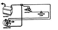
Figure 1.
1.
A basic wiring diagram showing charging circuit
connections is shown in Figure 1.
Refer to Section 6.1, Electrical System Wiring, for
additional information.
Figure 2.
F-262
|


