| |
TM 10-3930-671-24
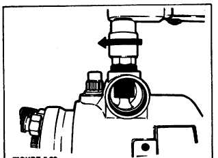
to the rear will cause compression of the governor spring
(Figure 5.18).
FIGURE 5.18.
STEP 19 Invert the pump and holding fixture in the vise.
Apply a light film of grease to the head locating screw.
Insert the screw and thread deeply into head hand tight.
Using a 7/16’ deep well socket and torque wrench,
tighten to specification.
NOTE
If screw is not seated properly into the head, the seal
may be sheared during tightening (Figures 5. 19a
and 5. 19b).
FIGURE 5.19b.
STEP 20 Install the cam advance screw (Figure 5.20).
Assemble the bristol socket cam advance screw wrench
and cam advance screw bushing into the advance screw
hole plug. Tighten the cam screw to the specified torque.
Check cam ring for freedom of movement (locking down
the screw can sometimes twist the cam). If cam is not
free, tap the screw lightly with a brass rod.
FIGURE 5.20.
STEP 21 Assemble the automatic advance components
(Figure 5.21a). Install the piston ring seal and ring into
FIGURE 5.19a.
F-243
|


