| |
TM 10-3930-671-24
FIGURE 5.13b.
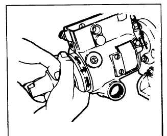
STEP 14 Rotate the head assembly until the head
locking screw holes line up with their corresponding
holes in the housing. Insert the two head locking screws
finger tight (Figure 5.14). Do not tighten with a wrench
until STEP 27.
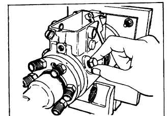
To prevent the governor weights from becoming
dislodged from the retainer, a drive shaft should now be
installed in the pump. When the pump is fully assembled,
the throttle should be wired in the wide open throttle
(WOT) position and the shaft may then be removed.
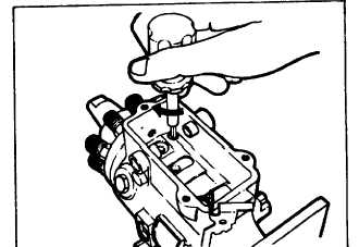
STEP 15 Install the vent wire screw assembly (Figure
5.15). Tighten to 25-30 in.-lbs. (3-3.5 Nom).
FIGURE 5.15.
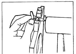
STEP 16 Assemble the metering valve arm, shim and
spring to the metering valve (Figure 5.16a). Exercise
care not to distort any of the components.
FIGURE 5.16a.
FIGURE 5.14.
F-241
|