| |
TM 10-3930-671-10
Know The Truck
Truck Components & Features
TA18 Brake System
Service Brake
Dual foot pedals are connected to two master cylinders. Service brakes can be applied with both pedals. Trucks have a
manual (not powered) brake system. The master cylinders apply pressure, through brake lines, to drum and shoe brakes
at drive wheels. Brakes are self-adjusting. Service brakes are mechanically actuated for parking. Brake system is a
closed circuit using silicon hydraulic brake fluid supplied from a separate reservoir.
Inching Brake
Left pedal is for normal inching control. Pushing gradually on pedal will smoothly disengage transmission. Pushing pedal
further will apply service brakes.
Parking Brake
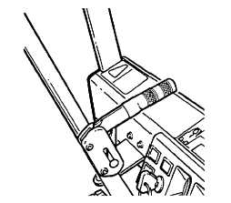
A parking brake is provided by mechanical actuation of
the service brakes. A hand-operated parking brake lever
mounted at the dash is connected by cables to the brake
assemblies, one to each drive wheel.
Main Hydraulic System/
Power Steering System
The parts of the main hydraulic system are the hydraulic
sump tank, main hydraulic pump, priority demand valve,
main control valve, hydraulic oil filter, and associated
hydraulic lines and hoses.
The hydraulic sump is a separate, removable tank bolted
in the right side compartment of the truck frame where it
is protected from damage. It has a large opening at the
top with a removable cover which includes the fill
tube/breather, oil level dipstick, and oil filter return line.
The cover is held on with a V-clamp for positive sealing
and ease of servicing. The sump breather is a standard
Clark part with a nominal 10 micron © 98.5% efficiency
rating.
The main hydraulic pump is mounted to an SAE pad on
the transmission driven by a silent chain from the engine
The main hydraulic control valve features adjustable
system pressure relief valves and a counterbalance
valve in the tilt circuit with a pressure compensated flow
control valve to control tilt speeds. All ports and
connecting lines are on the bottom surface of the valve.
The side shift attachment uses a single auxiliary section
on the outer (RH) side of the standard (lift/tilt only) main
valve.
The side shift attachment also has an adjustable relief
valve and can be assembled with optional flow controls
for 2.5, 4.0, 5.5, 7.0, or 10.0 gpm flow level.
The hydraulic system relief pressure level is "tuned"
(adjusted) to match the need of each truck rated
capacity. Maximum pressure is 3000 psi (20,700 kPa) .
A diagnostic demand valve allows access for checking
main hydraulic and steer system pressure.
E-43
|

