| |
TM 10-3930-669-20
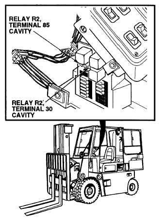
CONTINUITY TEST
(1) Set multimeter select switch to OHMS.
(2) Check continuity between relay R2,
terminal 85 cavity and a known good
ground.
(a) If there is no continuity, repair relay
R2 ground wire (see schematic
Appendix F)
(b) If there is continuity, relay R2
ground wire is OK.
VOLTAGE TEST
(1) Set multimeter select switch to VOLTS
DC.
(2) Connect positive (+) multimeter lead to
relay R2, terminal 30 cavity.
(3) Connect negative (-) multimeter lead to
a known good ground.
(4) Set MAIN POWER switch to ON
position (TM 10-3930-669-10).
(a) If there are not 22 to 24 vdc
present,
repair
wire
7
(see
schematic Appendix F).
(b) If there are 22 to 24 vdc present,
wire 7 is OK.
(5) Set MAIN POWER switch to OFF
position.
2-127
|