| |
TM 10-3930-664-24
6.
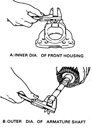
Measure armature shaft and bore clearance as
follows:
a.
Measure I.D. of shaft bore in magnetic switch
assembly.
b.
Measure O.D. of armature shaft.
c.
Subtract shaft O.D. from bore I.D. (A - B). Service
limit is 0.2 MM.
7.
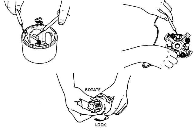
Inspect brush holder for damage to brushes or
springs. Check insulation for deterioration. Replace
brushes if less than 2/3 original length.
8.
Using multimeter, conduct brush holder continuity
test. If there is continuity, replace brush holder.
9.
Using multimeter, conduct yoke winding continuity
test. There shall be continuity.
10. Inspect clutch pinion to ensure free movement in
direction of starter rotation. Clutch shall lock if pinion
is rotated in opposite direction.
3-99
TM 10-3930-664-24
|


