| |
TM 10-3930-664-24
Section VI. ELECTRICAL SYSTEM MAINTENANCE
3-27.
ALTERNATOR REPAIR
This task covers: Suppression Capacitor Check, Disassembly, Cleaning, Inspection, Repair, Assembly, and Testing
INITIAL SETUP:
Tools and Test Equipment:
Equipment Condition:
General Mechanics Tool Kit (1, App. E)
Alternator removed (para. 2-55)
Digital Multimeter (6, App. E)
Test Set (2, App. E) (2 ea.)
Torch Kit, Soldering (29, App. E)
Puller Kit (26, App. E)
Rotor Test Stand (41, App. E)
Dial Indicator (17, App. E)
Arbor Press (25, App. E)
Feeler Gage (21, App. E) (3 ea.)
Materials / Parts:
Solder, Colophonium Tin (36, App. C)
O-Ring, Item 26 (1 ea.)
A.
SUPPRESSION CAPACITOR CHECK
1.
Remove capacitor lead from terminal B+.
2.
Connect multimeter between lead of capacitor and
terminal B-.
3.
Meter shall read 1.8 to 2.6 mF. Replace suppression
capacitor if value is not met.
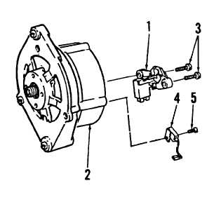
B.
DISASSEMBLY
1.
Remove transistor regulator (1) from alternator (2)
by removing screws (3). Remove suppression
capacitor (4) by removing screw (5).
2.
Before proceeding, match mark shields (6, 7) and
stator for ease of assembly.
3.
Remove four screws (8) and carefully separate drive
end shield (6) from ring end shield (7).
3-90
|