| |
TM 10-3930-664-24
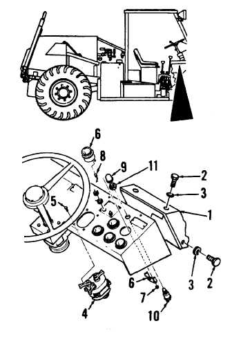
2-59. INSTRUMENT PANEL GAUGE, SWITCH, LIGHT REPLACEMENT
This task covers: Removal, Cleaning, Inspection, and Installation
INITIAL SETUP:
Tools and Test Equipment:
Equipment Condition:
General Mechanics Tool Kit (1, App. E)
Batteries disconnected (para. 2-78)
Instrument panel replacement
(para. 2-58), brace removed
A. REMOVAL
WARNING
Electrical shock hazard. Disconnect
battery ground cable or power source
prior
to
working
on
electrical
components. Failure to heed warning
could cause shock, injury or death. If
electrical shock occurs, administer
first aid and seek medical assistance.
1.
REMOVE LEFT AND RIGHT DASH COVERS
(1) BY REMOVING SIX SCREWS (2) AND SIX
WASHERS (3).
CAUTION
When disconnecting power
wires
from I terminal on gauges, tag wires
to
ensure
correct
installation.
Connecting power wire to S terminal
will destroy gauge.
2.
TAG AND DISCONNECT ELECTRICAL WIRES
FROM SWITCHES, GAUGES, AND LIGHTS AS
REQUIRED.
3.
REMOVE MASTER SWITCH (4), GAUGES (6),
AND ETHER SWITCH (10).
a.
Remove
master
switch
(4)
from
instrument panel by removing screws (5).
b.
Remove gauges (6) and gauge brackets
by removing nuts (7). Remove light kits
(8) from bottom of gauges.
c.
Remove rubber switch cover (9) from
ether switch (10). Remove ether switch by
removing nut (11).
2-179
|

