| |
TM 10-3930-664-10
1-22.
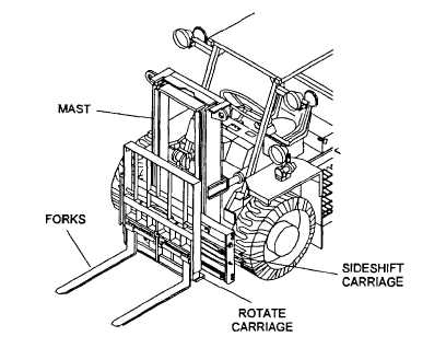
MAST ASSEMBLY
FORKS. Constructed of forged steel and mounted on the rotate carriage. Separation between fork arms is adjusted to
accommodate loads of varying width. Positioning notches on the rotate carriage and indexing lugs on the fork arms are
used to adjust the distance between fork arms and lock the fork arms in place.
ROTATE CARRIAGE. Steel frame Is attached to the sideshift carrier. Provides vertical support for the rear of the load
positioned on the forks and rotates the forks. Body of rotation cylinder is attached to the sideshift carrier and the cylinder
rod end is attached to the rotate carriage. Controlled by the rear joystick on the directional control valve. Moving the
joystick to the left causes the cylinder to extend and rotate the forks counterclockwise. Moving the joystick to the right
causes the cylinder to retract and rotate the forks clockwise.
LOAD BACKREST. Steel frame attached to the rotate carriage. Provides support and stability for the load positioned on
the forks. Load backrest can be removed for operating inside containers.
SIDESHIFT CARRIER. Steel frame supports the rotate carriage and forks. Hydraulic sideshift cylinder drives two chains
which sideshift the rotate carriage assembly. Controlled by the front joystick on the directional control valve. Moving
joystick to the left causes the cylinder to retract and moves the forks to the left. Moving joystick to the right causes the
cylinder to extend and moves the forks to the right.
MAST. Composed of three sections; inner rail, intermediate rail, and outer rail assemblies. Raises and lowers the
sideshift carrier along with the rotate carriage and forks. Rollers mounted on the sideshift carrier move in channels formed
by the inside of the I-beams used for the sides of the inner rail assembly. A chain, driven by the freelift cylinder, provides
the up and down movement of the sideshift carrier. Forks can be raised from ground level to 48 inches (122 cm) above
the ground by lifting the sideshift carrier. Rollers mounted on the inner rail move in channels formed by the inside of the I-
beams used for the sides of the intermediate rail assembly while rollers mounted to the intermediate rail move in the
channels which form the sides of the outer rail assembly. When the rod of the freelift cylinder reaches its maximum
extension, the two mainlift cylinders begin to operate. The mainlift cylinder rods are attached to the top of the intermediate
rail and lift both the intermediate rail and the inner rail as the rods extend. At the same time, the inner rail is lifted by two
chains driven by the same two mainlift cylinders so that the inner rail along with the sideshift carrier and forks is moved
upward out of the intermediate rail assembly. Through the combined movements of the sideshift carrier, intermediate rail,
and inner rail the forks can be raised to a height of 120 inches (305 cm) above ground level. Up and down movement of
the mast is controlled by the front joystick on the directional control valve. Pushing the joystick forward retracts the
cylinders and lowers the forks. Pulling the joystick back extends the cylinders and raises the forks.
1-14
|