| |
TM10-3930-660-34
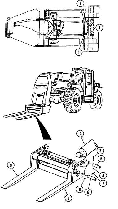
16-11.CARRIAGE ASSEMBLY - REPLACE (Cont’d)
1.
TAG AND DISCONNECT FOUR HOSES (1)
FROM FORK SIDESHIFT CYLINDERS.
2.
DISCONNECT CARRIAGE TILT CYLINDERS (2).
a.
Attach carriage assembly to a hoist through a
suitable sling.
b.
Take up slack in lifting sling to allow hoist to
support carriage assembly.
c.
Remove capscrew (3) and locknut (4) from tilt
cylinder pivot pin (5).Discard locknut (4).
d.
While supporting tilt cylinder (2) to prevent it
from dropping, remove tilt cylinder pivot pin
(5) using a pin puller.
e.
Carefully lower tilt cylinder (2) onto MLRS
frame.
f.
Repeat STEPS a-e for tilt cylinder on other
side.
3.
START ENGINE, TM10-3930-660-10.
4.
RETRACT CARRIAGE TILT CYLINDERS (2).
5.
SLOWLY LOWER BOOM UNTIL BASE OF
CARRIAGE JUST CONTACTS THE GROUND,
AND FORK TIPS ARE ABOUT ONE INCH
ABOVE THE GROUND.THIS TAKES WEIGHT
OFF OF CARRIAGE PIVOT PINS (6).
6.
SHUT OFF ENGINE, TM10-3930-660-10.
7.
PLACE WOOD BLOCK UNDER EACH FORK
TIP.
8.
REMOVE CARRIAGE PIVOT PINS (6).
a.
Remove capscrew (7) and locknut (8) from
carriage pivot pin (6). Discard locknut (8).
b.
Remove carriage pivot pin (6) using suitable
pin puller.
16-46
|