| |
TM10-3930-660-34
16-4. MAIN CONTROL VALVE ASSEMBLY - REPAIR (Cont’d)
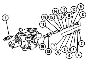
2.
IF REMOVAL WAS NECESSARY, ASSEMBLE
AND
INSTALL TWO RELIEF VALVES (20).
a. Install new O-ring (38) on body (37).
b. Install new O-ring (33) on poppet (35). Install
back-up ring (34).
c. Install poppet (36), poppet (35), piston (32) and
spring (31) into body (37).
d. Install new O-rings (28 and 30) onto plug (27).
e.
Install back-up ring (29) onto plug (27). Install plug
assembly (27) into body (37).
f.
Install poppet (26), spring (25) and adjusting
screw (24).
g. Install one new O-ring (23) into each nut (21 and 22).
h. Install nuts (21 and 22).
i.
Install two relief valve assemblies (20).
3.
IF REMOVAL WAS NECESSARY, ASSEMBLE
AND INSTALL TWO RELIEF VALVES (1).
a. Install new O-ring (19) on body (18).
b.
Install new O-ring (14) on poppet (13). Install
back-up ring (15).
c.
Install poppet (17), poppet (16), piston (13),
and spring (12) into body (18).
d. Install new O-rings (9 and 11) onto plug (8).
e.
Install back-up ring (10) onto plug (8). Install
plug assembly (8) into body (18).
f.
Install poppet (7), spring (6) and adjusting
screw (5).
g.
Install one new O-ring (4) into each nut (2 and
3).
h. Install nuts (2 and 3).
i.
Install two relief valve assemblies (1).
4.
INSTALL MAIN CONTROL VALVE ASSEMBLY,
TM10-3930-660-20.
5.
INSTALL BOOM CYLINDER FLOW CONTROL
VALVE, TM10-3930-660-20.
16-23
|

