| |
TM10-3930-660-34
16-4. MAIN CONTROL VALVE ASSEMBLY - REPAIR (Cont’d)
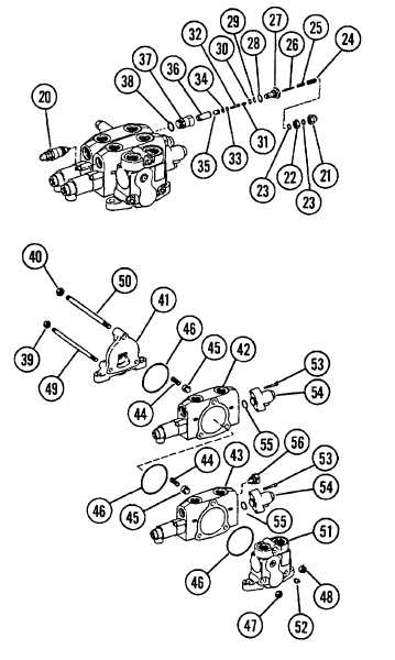
e. Remove body (18) and O-ring (19). Discard O-ring (19).
NOTE
Do not remove relief valves unless they are being replaced.
2.
REMOVE AND DISASSEMBLE TWO RELIEF VALVES
(20) IF NECESSARY.
a.
Remove nuts (21 and 22). Remove and discard two
seals (23) from nuts (21 and 22).
b. Remove adjusting screw (24), spring (25) and poppet
(26).
c.
Remove plug (27), O-ring (28), back-up ring (29) and
O-ring (30). Discard O-rings (28 and 30).
d.
Remove spring (31), piston (32), O-ring (33), back-up
ring (34) and poppets (35 and 36). Discard O-ring
(33).
e.
Remove body (37) and O-ring (38). Discard O-ring
(38).
3. DISASSEMBLE VALVE (39-68).
a.
Mark housing sections of valve. These marks will be
used for assembly.
b.
Remove two nuts (39), one nut (40) and outlet section
(41).
NOTE
Be careful not to loose springs (44) and poppets
(45) when removing housing sections.
c. Remove housing sections (42 and 43).
d. Remove two springs (44) and two poppets (45).
16-20
|

