| |
TM10-3930-660-34
16-4. MAIN CONTROL VALVE ASSEMBLY - REPAIR
This task covers:
a.
Removal
c.
Inspection
e.
Pre-Load Check of Bearing
b.
Disassembly
d.
Reassembly
f.
Installation
INITIAL SETUP:
Tools
Tool Kit, Automotive Mechanics
Shop Equipment, Automotive
Maintenance, Common #2
Less Power
Equipment Condition
Boom cylinder flow control valve removed,
TM10-3930-660-20.
Main control valve assembly removed,
TM10-3930-660-20.
Materials/Parts
Hydraulic Oil (App. B, Item 35)
Lint-Free Rags (App. B, Item 38)
O-rings (4, 9, 11, 14, 19, 23, 28, 30,
33, 38, 46, 55, 65, 66)
DISASSEMBLY
NOTE
Do not remove relief valves unless they are being replaced.
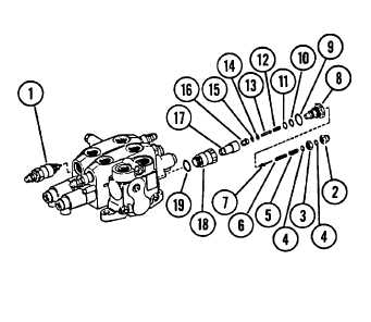
1. REMOVE AND DISASSEMBLE TWO MAIN RELIEF VALVES
(1) IF NECESSARY.
a.
Remove nuts (2 and 3). Remove and discard two seals
(4) from nuts (2 and 3).
b. Remove adjusting screw (5), spring (6) and poppet (7).
c.
Remove plug (8), O-ring (9), back-up ring (10) and O-
ring (11). Discard O-rings (9 and 11).
d.
Remove spring (12), piston (13), O-ring (14), back-up
ring (15) and poppet (16 and 17). Discard O-ring (14).
16-19
|

