| |
TM10-3930-660-34
8-5.
FRONT DIFFERRENTIAL CARRIER ASSEMBLY - REPLACE/REPAIR/ADJUST (Cont’d)
5.
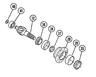
DISASSEMBLE BEVEL PINION (12) AND
BEARING CAGE (28).
a. Place bevel pinion (12) and
bearing cage (28) in a press with
splined end at the top of
assembly.
b. Support bearing cage (28) under
flange area with metal or wood
blocks.
c. Use a press or leather mallet and
suitable driver to remove bevel
pinion (12) from bearing cage
(28).
d. Remove outer bearing (35) from
bearing cage (28).
e. Use a suitable puller to remove
inner bearing cone (36) and
bearing spacer (37) from bevel
pinion (12).
f.
Use a suitable puller to remove
inner bearing cup (38) and outer
bearing cup (39) from bearing
cage (28).
g. Install a soft metal cover over
vise jaws to protect bevel
pinion (12). Place bevel pinion
(12) in a vise.
h. Use expanding snap ring pliers to
remove snap ring (40) from end of
bevel pinion (12).
i.
Use a suitable puller to remove
bearing (41) from spigot end of
bevel pinion (12).
CLEANING
See Cleaning Instructions, para. 2-10.
INSPECTION
See Inspection Instructions, para. 2-11.
8-15
TM10-3930-660-34
|