| |
TM10-3930-660-34
6-9.
ELECTRIC JOYSTICK ASSEMBLY - REPAIR/TEST/ADJUST (Cont’d)
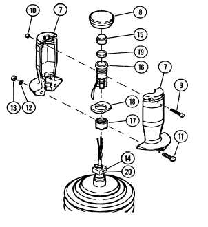
d. Separate handle sections (7) and remove
them from shaft coupling (14).
e. Remove actuating button (15).
f.
Remove pushbutton switch (16) nut (17) and flange
(18) as a unit from handle sections (7).
2.
UNSOLDER FOUR LEADS FROM PUSHBUTTON
SWITCH (16) AND DISASSEMBLE PARTS (17)
THROUGH (19).
a. Carefully unsolder all leads from pushbutton switch
(16).
b. Remove nut (17) and flange (18) rom pushbutton
switch (16).
c. Remove cover (19) from pushbutton switch (16).
INSPECTION
1.
CHECK FOR LOOSE OR DISCONNECTED PLUGS AT
SWITCHES (1) THROUGH (4).
2
.
CHECK ALL SWITCHES FOR LOOSE
MOUNTING HARDWARE OR VISIBLE
DAMAGE.
INSTALLATION OF HANDLE PUSHBUTTON SWITCH
1.
ASSEMBLE PARTS (17) THROUGH (19) AND
SOLDER FOUR LEADS TO
PUSHBUTTONSWITCH (16)
a. Install cover (19) to pushbutton switch.
b. Install flange (18) and nut (17) to pushbutton
switch (16).
NOTE
Pin numbers are printed on body of pushbutton switch
(16).
c
Solder green electrical lead of joystick to pin 1
of pushbutton switch (16).
6-34
|

