| |
TM10-3930-660-34
6-4. STARTER - REPAIR (Cont’d)
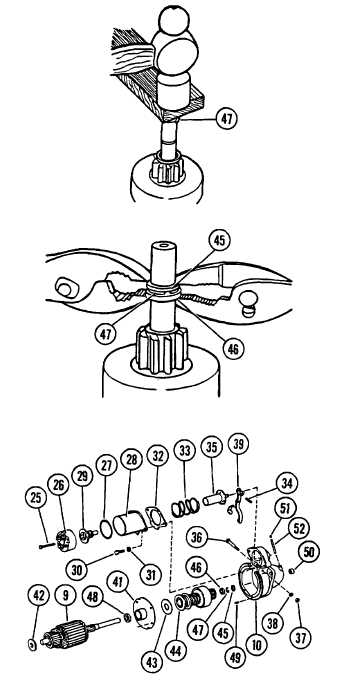
b. Install pinion stop (46) (cupped
side facing out) and retaining ring
(47) on armature shaft. Retaining
ring (47) may have to be forced
over end of armature shaft using a
hammer and piece of wood, as shown.
c. Place thrust collar (45) on
retaining ring (47) and force
pinion stop (46) over retaining
ring (47), using two pliers as
shown.
4. ASSEMBLE ARMATURE/MOTOR DRIVE AND
SOLENOID SWITCH TO DRIVE HOUSING (10).
a. Clamp drive housing (10) in a
padded vise.
b. Position center bearing retainer (41)
to drive housing (10).
c. Place shift lever (39) in drive
housing (10) and secure with screw
(36), nut (37) and new lockwasher
(38).
d. Install plunger (35) and pin (34).
e. Install plunger return spring (33),
and new gasket (32).
f. Install solenoid switch (28), two
screws (30) and two new lockwashers
(31).
g. Position contact (29) between cover
(26) and solenoid switch housing
(28). Align new gasket (27) and
secure cover (26) to solenoid
switch housing (28) with two
capscrews (25).
5. INSTALL PARTS IN FIELD FRAME (8).
NOTE
If pole shoes (23) have one long lip,
install pole shoes so long lip points in
direction of armature rotation. Also,
observe match marks made before removal.
6-16
|

