| |
TM10-3930-660-34
6-3. ALTERNATOR - REPAIR/TEST (Cont’d)
5. CONNECT STATOR TERMINAL CLIPS (17)
TO DIODE TRIO (18) AND RECTIFIER
BRIDGE (23) WITH THREE NUTS
(16).
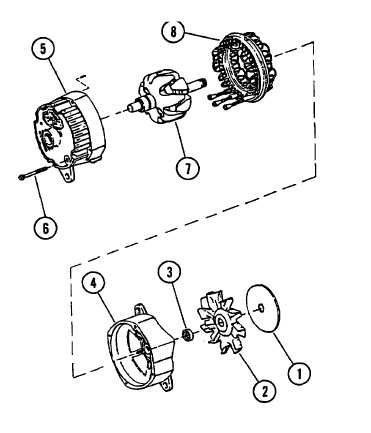
6. PLACE STATOR (8) ON SLIP RING END
FRAME (5).
7. ASSEMBLE SLIP RING END FRAME (5) AND
DRIVE END FRAME (4).
CAUTION
Be careful as rotor (7) is placed in slip
ring end frame (5), not to damage brushes
or seal (41).
NOTE
To secure brushes during rotor (7)
installation, push brushes into brush and
holder assembly (20) and insert a stiff
piece of wire through hole provided in
slip ring end frame (5).
a. Position drive end frame (4), with
rotor (7), on slip ring end frame
(5). Align match marks that were
made during disassembly.
b. Remove wire used to hold up brushes
during rotor (7) installation.
(NOTE above).
c. Install and tighten four through
bolts (6).
d. Install collar (3), fan (2) and
baffle (1) on rotor shaft.
7. INSTALL ALTERNATOR PULLEY,
TM10-3930-660-20.
8. INSTALL ALTERNATOR TO ENGINE,
TM10-3930-660-20.
6-10
|

