 |
|||
|
|
|||
|
|
|||
| ||||||||||
|
|
 TM 10-3930-660-24-2
REAR DIFFERENTIAL CARRIER ASSEMBLY MAINTENANCE - CONTINUED
0298 00
ADJUSTMENT
1.
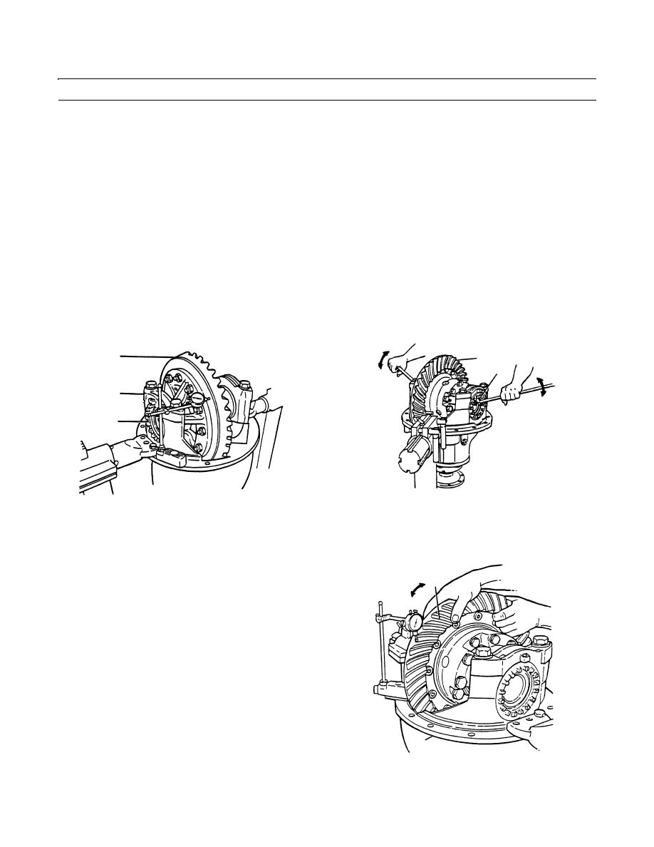
Attach a dial indicator on the mounting flange of the differential carrier (7).
2.
Adjust the dial indicator so that the plunger is against the back surface of the ring gear (8). Adjust dial indicator to zero.
CAUTION
When turning bearing adjusting rings, use a large screwdriver that engages two or more opposite notches in
the ring. Failure to engage at least two notches could cause damage to adjusting ring lugs.
3.
Loosen the bearing adjusting ring (3) opposite ring gear (8) so that a small amount of end play shows on dial indicator.
Move differential assembly with ring gear (8) left and right with suitable pry bars while reading dial indicator. DO NOT
allow pry bars to touch bearing (9 thru 10).
4.
Tighten bearing adjusting ring (3) opposite ring gear (8) so that no end play shows on dial indicator. Move the differen-
tial assembly and ring gear (8) left and right as needed to be sure no end play is present.
5.
Tighten each bearing adjusting ring (3) one notch from the zero end play measured in step 4.
8
8
3
7
3
409-1303
409-1302
6.
Check runout of ring gear (8). Attach dial indicator on mounting flange of differential carrier (7). Adjust dial indicator
so that plunger is against back surface of ring gear (8).
7.
Adjust dial indicator to zero and rotate differential
assembly and ring gear (8) and read dial indicator. If
8
runout of ring gear (8) exceeds 0.008 in. (0.20 mm),
remove differential assembly and ring gear (8) and
inspect differential assembly for problem. Replace
defective parts and install differential assembly and
ring gear (8) into differential carrier (7). Repeat pre-
load adjustment of differential bearings.
8.
To adjust backlash of ring gear (8), attach a dial indi-
cator to the mounting flange on differential carrier (7).
9.
Adjust dial indicator so that plunger is against the
tooth surface on ring gear (8).
7
409-1304
0298 00-12
|
|
Privacy Statement - Press Release - Copyright Information. - Contact Us |
