 |
|||
|
|
|||
|
|
|||
| ||||||||||
|
|
 TM 10-3930-660-24-2
FRONT DIFFERENTIAL CARRIER ASSEMBLY MAINTENANCE - CONTINUED
0296 00
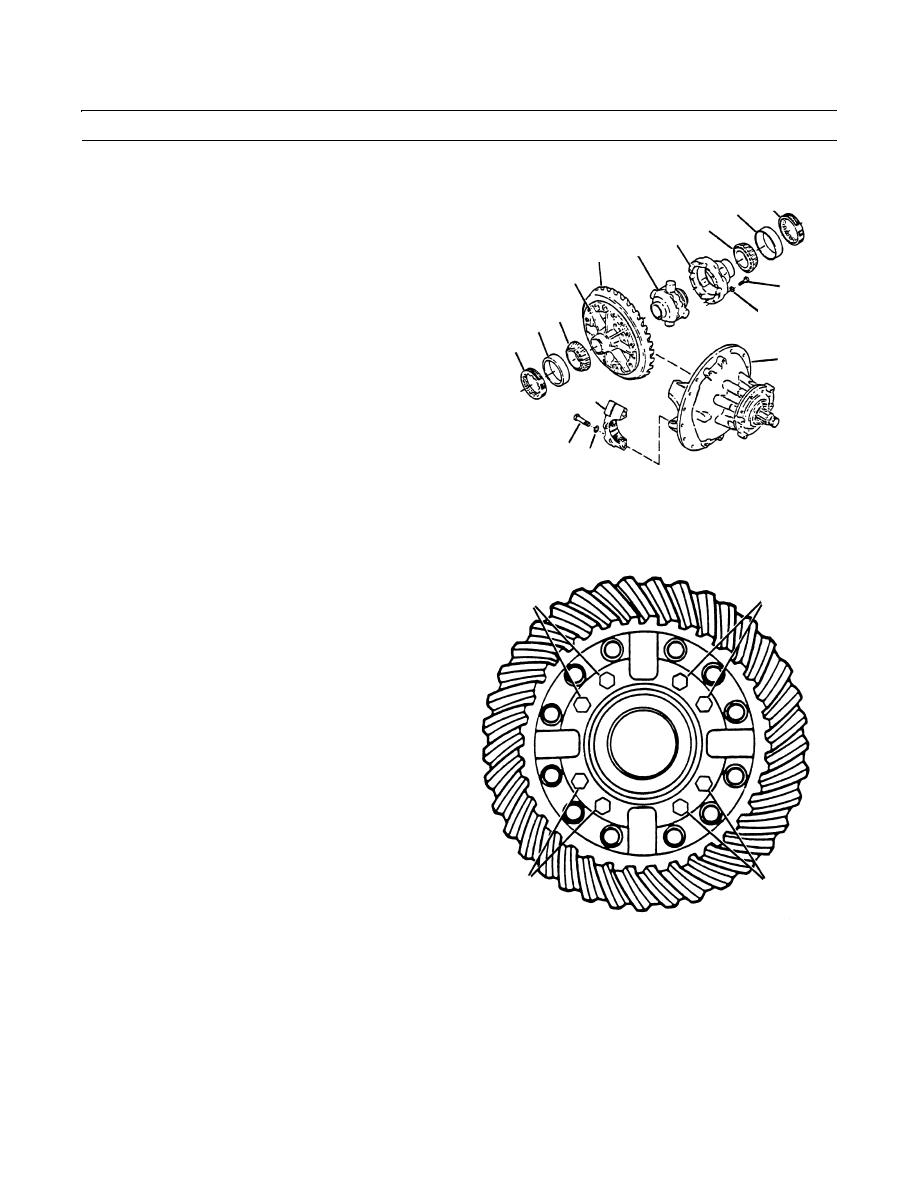
ASSEMBLY - CONTINUED
41.
Use a press and sleeve to install bearing cone (10) on
4
9
flange case half (17).
11
16
12
42.
Use a press and sleeve to install bearing cone (11) on
13
plain case half (16).
17
14
43.
Apply clean lubricant to inside surfaces of both case
10
halves (16 and 17) and no-spin differential (12).
15
9
4
44.
Place flange case half (17) on bench, ring gear (13)
8
teeth up.
2
45.
Install no-spin differential (12) into flange case half
(17).
46.
Place plain case half (26) over flange case half (17)
67
and no-spin differential (12). Rotate plain case half
409-1249
(16) as needed to align match marks.
47.
Apply loctite to eight capscrews (14). Install four of the eight capscrews (14) and four flatwashers (15) at opposing pairs
(X and Y) into case halves (16 and 17).
CAUTION
Y
X
14,15
14,15
Spacing between four initially installed
capscrews must be even to prevent uneven
pressure on case halves when torquing.
Failure to do so could cause component
failure.
48.
Torque four capscrews (14) to 60-75 lb-ft (81-102
Nm).
NOTE
Torque capscrews in pairs on opposing
sides of ring gear.
49.
Install remaining four capscrews (14) and four flat-
washers (15). Torque capscrews to 60-75 lb-ft (81-102
14,15
14,15
Nm).
Y
X 409-1250
50.
Remove no spin retaining bolt, flatwashers and wing
nut.
NOTE
When installing bearing cups, apply loctite to bearing bores of differential carrier legs and bearing caps. Do
not apply loctite to adjusting ring threads.
Clean and dry bearing cups, bores of differential carrier, legs and bearing caps.
51.
Apply thin film of gear oil to inner diameter of the bearing cups (9) and on both bearing cones (10 and 11).
0296 00-10
|
|
Privacy Statement - Press Release - Copyright Information. - Contact Us |