 |
|||
|
|
|||
|
|
|||
| ||||||||||
|
|
 TM 10-3930-660-24-2
TRANSMISSION OIL PUMP MAINTENANCE - CONTINUED
0294 00
DISASSEMBLY - CONTINUED
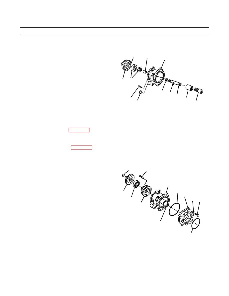
8.
Remove two piece geroter (19).
20
25
2
9.
Remove bearing (20) from retainer (17).
10.
Remove woodruff key (21) from key way in shaft
(14).
11.
Remove sleeve adapter (22) and sleeve spacer (23).
19
12.
Remove shaft (14) and thrust race (24).
17
13.
Remove bearing (25) from housing (2).
14.
Remove capscrew (26) and expansion plug (27) if
24
21
necessary.
14
26
23
27
22
409-1224
CLEANING
See Cleaning instructions (WP 0316 00).
INSPECTION
See Inspection instructions (WP 0317 00).
ASSEMBLY
1.
If removal was necessary, install expansion plug (27)
18
13
and capscrew (26).
2.
Install bearing (25) 0.015 in. (0.381 mm) below sur-
face in housing (2).
2
3.
Install thrust race (24) and woodruff key (21) on shaft
11
(14). Insert shaft (14) in housing (2).
15
8
10
9
16
4.
Install bearing (20) in retainer (17).
17
5.
Install two piece geroter (19) on shaft (14). The
geroter must assemble freely over woodruff key (21)
in shaft (14).
6.
Install retainer (17) on housing (2). Ensure that scribe
14
marks align.
7.
Apply alumilastic to threads of capscrews (18) and
12
409-1223
install six capscrews (18). Torque capscrews (18) to
17 lb-ft (23 Nm).
8.
Install sleeve spacer (23) and sleeve adapter (22) on shaft (14).
9.
Install bearing (16) and gear (15) on end of shaft (14).
10.
Install snap ring (13).
0294 00-2
|
|
Privacy Statement - Press Release - Copyright Information. - Contact Us |
