 |
|||
|
|
|||
|
|
|||
| ||||||||||
|
|
 TM 10-3930-660-24-2
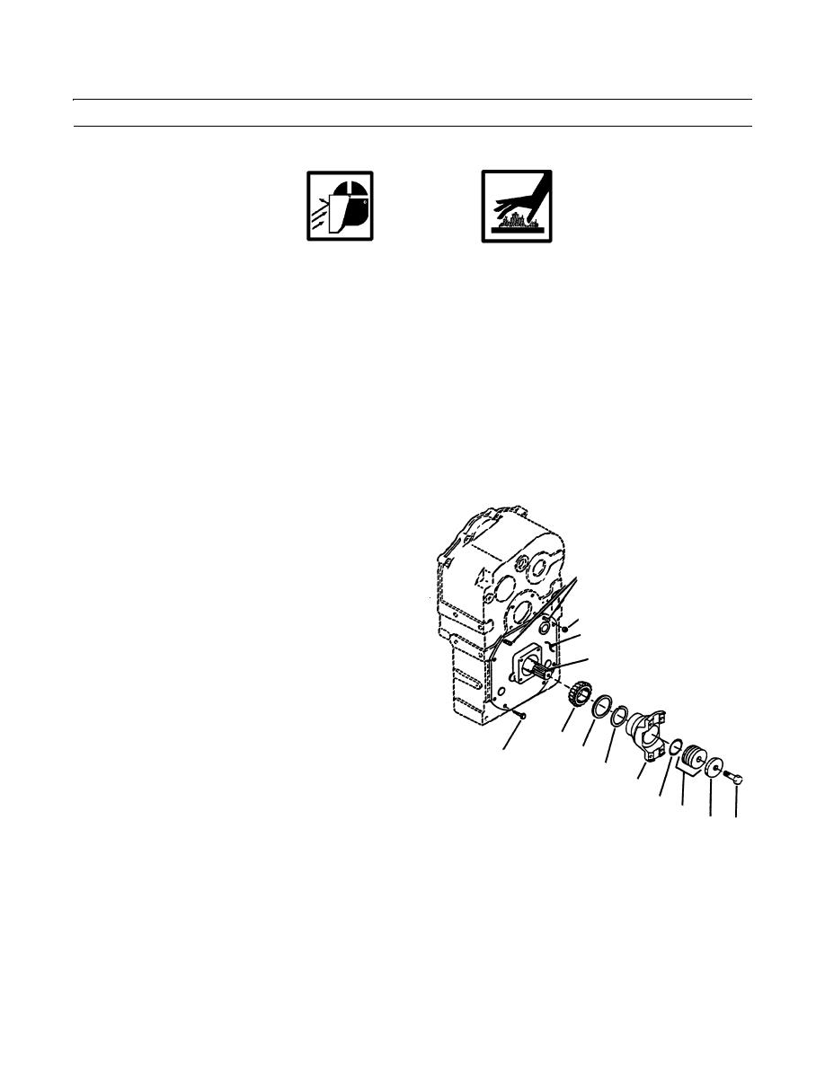
TRANSMISSION OUTPUT SHAFT MAINTENANCE - CONTINUED
0291 00
INSTALLATION
WARNING
Eye protection must be worn when performing maintenance where components or particles could fly out
during procedure. Failure to take precautions could cause injury to personnel.
Wear gloves and proper clothing while handling hot bearing cones. Failure to follow this warning could
cause injury to personnel.
CAUTION
Bearing cones must not be heated above 300F (149C). Freezing bearing cups is acceptable to aid for
installation.
1.
Install new oil seal (25) and bearing cup (24) in main case.
2.
If removal was necessary, install plug (23).
3.
If removal was necessary, install plug (22).
4.
Install bearing cup (21) and new oil seal (20) in output cap (10).
5.
Place case in vertical position. Install output shaft (7) with spacer screws to locate it in main case. Ensure that output
shaft (7) is installed straight and finished material of output shaft (7) yoke end is visible in front of seal.
6.
Install bearing cone (8), thrust race (9) and snap ring
(6) onto output shaft (7).
7.
Lay case down with output shaft (7) up. Install a new
O-ring (19) in groove of output cap (10).
13
8.
Install bearing cone (16) in bearing cup (21).
9.
Place gear (15) in baffle pan (14). Install baffle pan
12
(14) and two capscrews (17) to output cap (10).
10
10.
Install shims (18).
7
11.
Use two studs (13) as guide and carefully install out-
put cap (10) with shims (18) on main case. Use care to
prevent damage to oil seal (20) and O-ring (19).
12.
Install two nuts (12) and two capscrews (11). Ensure
8
that output shaft (7) spins freely.
9
11
NOTE
6
2
If a new yoke was installed, adjust shims
3
to obtain 0.005 in. (0.127 mm) gap
5
between yoke face and washer.
4
1
13.
Install yoke (2), new O-ring (3), shims (5), washer (4)
409-1211
and capscrew (1).
14.
Install a dial indicator to read shaft end play.
15.
Pull up on output shaft (7) and read end play on dial indicator.
16.
If end play is not within 0.000 to 0.004 in. (0.000 to 0.101 mm), adjust shims (5) as necessary to bring end play within
specifications.
17.
Remove indicator and base.
0291 00-3
|
|
Privacy Statement - Press Release - Copyright Information. - Contact Us |
