 |
|||
|
|
|||
|
|
|||
| ||||||||||
|
|
 TM 10-3930-660-24-2
ALTERNATOR ASSEMBLY MAINTENANCE (165 HP) - CONTINUED
0285 00
DISASSEMBLY - CONTINUED
13.
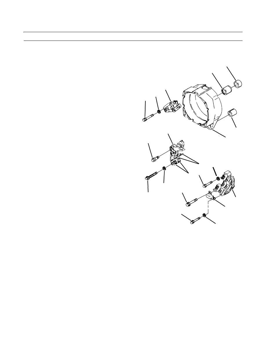
Remove screw (34), washer (35), insulated screw (36), and capacitor (37) from rectifier bridge assembly (21).
14.
Remove screw (38), washer (39), and rectifier bridge
46
assembly (21) from rear frame (7).
45
15.
Remove insulated screw (40), screw (41), washer (42),
and brush holder assembly (29) from rear frame (7).
20
16.
Remove screw (43), washer (44), and regulator (20)
from rear frame (7).
44
43
NOTE
If roller bearing is not being removed, apply
pressure sensitive tape over it for protection
against dirt. Do not use friction tape or other
tape that will leave a residue behind.
29
49
17.
Use press to remove roller bearing (45) and cap (46)
7
from rear frame (7). Discard roller bearing (45).
40
18.
Remove two brushes (47), and two springs (48) from
brush holder assembly (29).
19.
Use press to remove bushing (49) from rear frame (7).
Discard bushing.
47
39
38
48
42
36
41
21
37
34
35
409-1865
TR01428
0285 00-3
|
|
Privacy Statement - Press Release - Copyright Information. - Contact Us |