 |
|||
|
|
|||
|
|
|||
| ||||||||||
|
|
 TM 10-3930-660-24-2
CAMSHAFT, GEAR AND BUSHING MAINTENANCE - CONTINUED
0278 00
INSPECTION - CONTINUED
7.
Measure valve lobe diameters at peak of lobe. Minimum allowable intake valve lobe diameter at peak of lobe is 1.852
in. (47.04 mm). Minimum allowable exhaust valve lobe diameter at peak lobe is 1.841 in. (47.04 mm).
8.
Measure fuel lift pump lobe diameter. Minimum allowable fuel lift pump lobe diameter is 1.398 in. (35.5 mm).
9.
Inspect camshaft gear. If measured backlash is not 0.003 to 0.013 in. (0.076 to 0.33 mm).
10.
Inspect gear teeth for damage or excessive wear.
11.
Check for cracks at roots of gear teeth.
12.
Examine thrust plate for damage, distortion or excessive wear.
13.
Discard thrust plate if measured camshaft end play is not 0.007 to 0.011 in. (0.177 to 0.279 mm). Also check for
enlarged thrust plate slot in camshaft if end play is excessive.
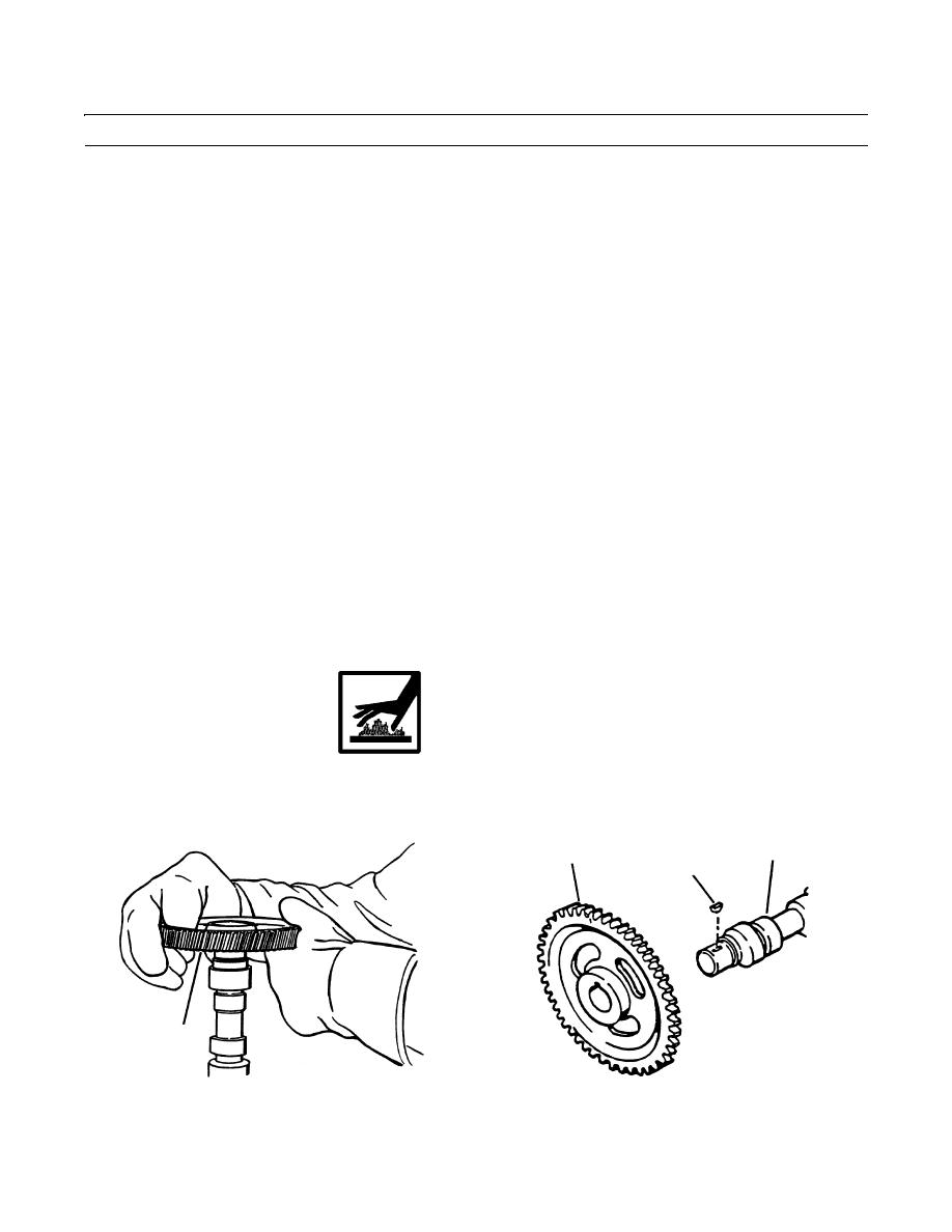
ASSEMBLY
1.
Install key (6) in camshaft (3).
2.
Install gear (4).
3.
Apply lubriplate to gear mounting surface of camshaft (3).
4.
Heat gear (4) in an oven to 250F (121C) for 45 minutes.
WARNING
Wear protective gloves to handle gear. Gear is hot and can cause severe burns.
5.
Install gear (4) on camshaft (3) with timing marks away from camshaft and gear tight against shoulder of camshaft.
3
4
6
4
409-1022
409-1021
0278 00-4
|
|
Privacy Statement - Press Release - Copyright Information. - Contact Us |
