 |
|||
|
|
|||
|
|
|||
| ||||||||||
|
|
 TM 10-3930-660-24-2
CARRIAGE ASSEMBLY REPLACEMENT - CONTINUED
0260 00
REMOVAL - CONTINUED
4.
Remove capscrew (3) and locknut (4) from tilt cylin-
der pivot pin (5). Discard locknut.
5.
While supporting tilt cylinder (2) to prevent it from
dropping, remove tilt cylinder pivot pin (5) using a pin
puller.
6.
Carefully lower tilt cylinder (2) onto MLRS frame.
7.
Repeat steps 3 thru 6 for tilt cylinder on other side.
8.
Start engine (TM 10-3930-660-10).
9.
Slowly lower boom until base of carriage just contacts
the ground, and fork tips are about one inch above the
ground. This takes weight off of carriage pins (6).
2
10.
Shut off engine (TM 10-3930-660-10).
11.
Place wood block under each fork tip.
3
12.
Remove carriage pivot pins (6).
5
13.
Remove capscrew (7) and locknut (8) from carriage
pivot pin (6). Discard locknut.
9
14.
Remove carriage pivot pin (6).
4
7
15.
Repeat steps 13 and 14 to remove second carriage
pivot pin (6).
8
6
16.
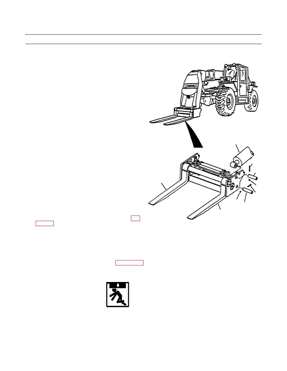
If necessary, remove forks (9) (WP 0186 00).
9
409-1395
17.
If necessary, remove fork sideshift cylinders (WP
INSTALLATION
NOTE
Remove caps and plugs as hoses are installed. Wipe all sealing surfaces on valve and hoses clean and dry.
1.
If removed, install fork sideshift cylinders (WP 0310 00).
2.
If removed, install forks (9) (WP 0186 00).
WARNING
Use caution when handling heavy parts. Provide adequate support and use assistance during procedure.
Ensure that any lifting device used is in good condition and of suitable load capacity. Keep clear of heavy
parts supported only by lifting device. Failure to follow this warning may cause injury or death.
3.
Using a hoist and sling, move carriage assembly into position on MLRS attachment.
0260 00-3
|
|
Privacy Statement - Press Release - Copyright Information. - Contact Us |