 |
|||
|
|
|||
|
|
|||
| ||||||||||
|
|
 TM 10-3930-660-24-2
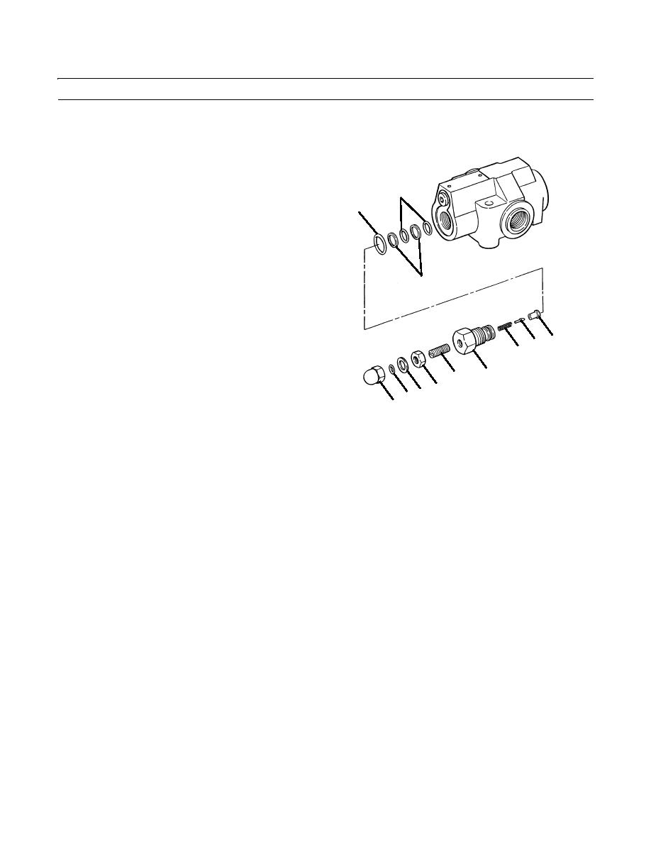
FRAME TILT/BRAKES RELIEF VALVE REPAIR - CONTINUED
0258 00
ASSEMBLY - CONTINUED
3.
Install new O-ring (15) in seat (19).
4.
If removal was necessary, install screw (17) and
retainer (16) on poppet (18).
11
5.
Install poppet assembly (14) and spring (13) into body
10
(20).
6.
Install two new O-rings (11) and new O-ring (10) on
cap (9). Ensure that back-up rings (12) are correctly
positioned.
7.
Install spring (6), plunger (7) and seat (8) in cap (9).
12
8.
Install cap (9). Ensure that spring (13) is positioned
over seat (8).
9.
Install setscrew (3) using the same number of turns as
8
7
was noted during Disassembly.
6
10.
Install jamnut (1) and tighten to hold setting.
9
3
1
11.
Install two new O-rings (5) with sealing washers (4).
54
2
12.
Hold jamnut (1) in position and install acorn nut (2).
409-4103
13.
Install frame tilt/brakes relief valve (WP 0178 00).
14.
Operate vehicle, check for proper operation and leaks (TM 10-3930-660-10).
END OF WORK PACKAGE
0258 00-3/(-4 Blank)
|
|
Privacy Statement - Press Release - Copyright Information. - Contact Us |
