 |
|||
|
|
|||
|
|
|||
| ||||||||||
|
|
 TM 10-3930-660-24-2
PISTON PUMP MAINTENANCE - CONTINUED
0256 00
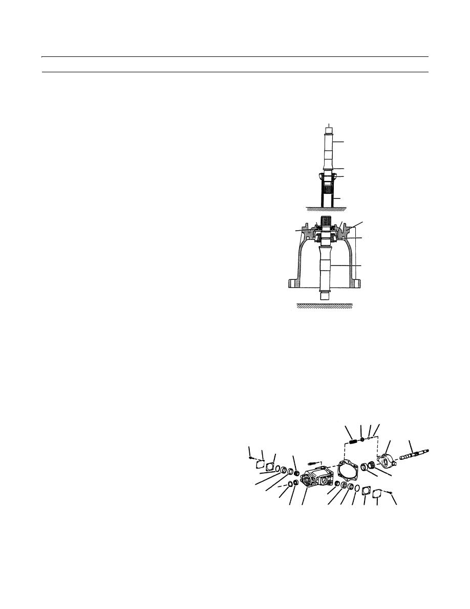
ASSEMBLY - CONTINUED
3.
Install new drive shaft bearing (38) and seal (41).
4.
Use fabricated tool and an arbor press to press shaft
ARBOR PRESS HERE
(15) through bearing (38). Press shaft until bearing
(38) bottoms against drive shaft (15) shoulder.
15
5.
Use fabricated tool and an arbor press to install new
bearing race (39) into housing (6). Press race until it
bottom against housing shoulder.
SHOULDER
6.
Install shaft (15) into housing (6) and check that bear-
38
ing rollers (38) move freely in bearing race (39) as
shaft is turned. Remove shaft (15) from housing.
1-1/2 IN. HEAVY WALL
7.
Use fabricated tool and an arbor press to install new
TUBING 6 IN. LONG
409-1481
shaft seal (41) into housing (6). End of seal (41) must
39
40
6
be positioned 0.25 in. (6.35 mm) from edge of housing
41
(6) (just below retaining ring (40) groove).
38
8.
Wrap plastic tape around spline end of driveshaft (15)
to prevent damage to shaft seal (41).
15
409-1482
9.
Place housing (6) on a clean, flat surface with shaft seal (41) end down.
10.
Insert spline end of driveshaft (15) into housing (6). Position driveshaft so that front shaft bearing (38) is inside bearing
race (39).
11.
Install yoke spring (35) and seat (34) into housing (6).
12.
Install yoke (26) into housing (6).
13.
Install pintle bearings (31) on each end of yoke (26) and install bearing race (30).
14.
Install bearing spacer (33) at one pintle end.
15.
Install new O-ring (32) against spacer and into groove
34 36 37
35
at one pintle end.
26
15
16.
Install a 0.010 in. (0.254 mm) shim under pintle cover
28 29
(29) at one pintle end.
27 31
17.
Install four pintle cover screws (28) into pintle cover
installed in step 18 above and torque screws to 175-
32
39 38
185 lb-in. (20-21 Nm).
33
18.
Place housing (6) on its side so other end of pintle is
30
31
facing up. Install bearing spacer (33).
40
30 33 32 27 29
41 6
28
409-1483
19.
Turn yoke (26) back and forth to seat bearings (31) in bearing races (30).
20.
Install correct pintle shims (27).
0256 00-7
|
|
Privacy Statement - Press Release - Copyright Information. - Contact Us |
