 |
|||
|
|
|||
|
|
|||
| ||||||||||
|
|
 TM 10-3930-660-24-2
FRONT DIFFERENTIAL CARRIER ASSEMBLY REPLACEMENT - CONTINUED
0243 00
REMOVAL
WARNING
Use caution when handling heavy parts. Provide adequate support and use assistance during procedure.
Ensure that any lifting device used is in good condition and of suitable load capacity. Keep clear of heavy
parts supported only by lifting device. Failure to follow this warning may cause injury or death.
1.
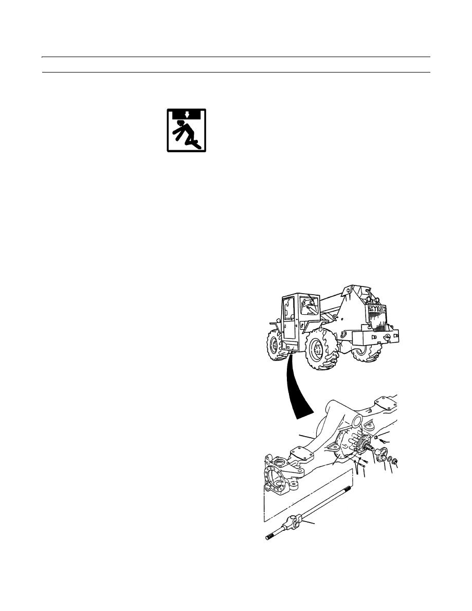
Remove axle shafts (1).
2.
Remove differential carrier (2) from axle housing (3).
3.
Carefully tip axle assembly so that front differential carrier (2) faces up.
4.
Reinstall companion flange (4), washer (5) and nut (6) that were removed with park brake assembly. The drive yoke will
provide a lifting point for differential carrier (2) during removal.
NOTE
Capscrews from differential carrier to axle
housing are of three different sizes. Note
size, location and quantity of capscrews
when removing for correct location during
replacement.
5.
Remove twelve capscrews (7), twelve flatwashers (8),
two capscrews (9), two capscrews (10) and four flat-
washers (11) from differential carrier (2).
6.
Use a leather or rubber mallet to loosen differential
carrier (2) in axle housing.
7.
Use a sling placed around bevel pinion, behind com-
panion flange (4), to lift and support the differential
carrier (2) during removal.
8.
Carefully remove differential carrier (2) from axle
8
3
housing (3).
7
9.
Place differential carrier (2) on stand or bench, with
ring gear up. Clamp securely.
9,12
2
4 56
11 10
1
409-1236
10.
Remove companion flange (4), nut (6) and washer (5) from bevel pinion (12).
0243 00-2
|
|
Privacy Statement - Press Release - Copyright Information. - Contact Us |