 |
|||
|
|
|||
|
|
|||
| ||||||||||
|
|
 TM 10-3930-660-24-2
FRONT AXLE ASSEMBLY REPLACEMENT - CONTINUED
0241 00
REMOVAL - CONTINUED
WARNING
Do NOT remove hydraulic tank filler cap or disconnect or remove any hydraulic system line or fitting unless
hydraulic system pressure has been relieved. Hydraulic system pressure can be over 3,000 psi (20685 kPa),
even with engine and pump OFF. After maintenance, tighten all connections before applying pressure.
Escaping hydraulic fluid under pressure can penetrate the skin, causing injury or death.
At operating temperature hydraulic oil is hot. Allow hydraulic oil to cool before disconnecting any hydrau-
lics. Failure to do so could result in injury.
CAUTION
Wipe area clean around all hydraulic connections to be opened during removal. Cap oil lines and plug holes
after removing lines. Contamination of the hydraulic system could result in premature failure.
NOTE
If more than one hydraulic line is to be
removed, tag and identify lines to ensure
proper installation. Use container to catch
any hydraulic oil that may drain from the
system.
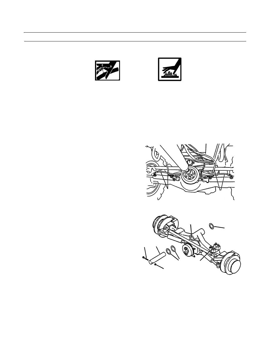
9.
Disconnect front steering cylinder hydraulic supply
hoses (7).
7
7
409-1229
10.
Use a floor jack to support weight of front axle assem-
bly.
B
11.
Remove locknut (8) and retaining capscrew (9). Dis-
10
card locknut.
11
9
NOTE
Note the location and quantity of washer
10
spacers during removal. Keep washer
A
spacers together as a set.
8
12.
Remove axle aligning rod (11) and washer spacers
409-1230
(10).
13.
Place a steel bar, minimum 1 in. diameter and 6 ft long (2.5 cm diameter and 183 cm long), in the tilt cylinder rod pivot
pin mounting hole (A). The bar will prevent the axle assembly from rotating when the axle is removed.
14.
Lower floor jack and roll axle assembly to the front from under vehicle, using floor jack and 6 ft (183 cm) bar, to prevent
axle assembly from rotating.
15.
Raise axle assembly using floor jack. Support axle assembly and wheels using stands.
0241 00-4
|
|
Privacy Statement - Press Release - Copyright Information. - Contact Us |
