 |
|||
|
|
|||
|
|
|||
| ||||||||||
|
|
 TM 10-3930-660-24-2
ROCKER LEVER ASSEMBLY MAINTENANCE - CONTINUED
0216 00
REMOVAL - CONTINUED
1.
Loosen two adjusting screw nuts (1).
4
1
9
2.
Loosen two adjusting screws (2).
11
3
3.
Remove capscrew (3), capscrew (4), and remove
5
rocker arm assembly (5).
87
4.
Remove push rods (6).
12
10 1
2
DISASSEMBLY
9
6
NOTE
2
Keep each rocker arm assembly together as a
set.
6
Remove expansion plug only if necessary.
8
7
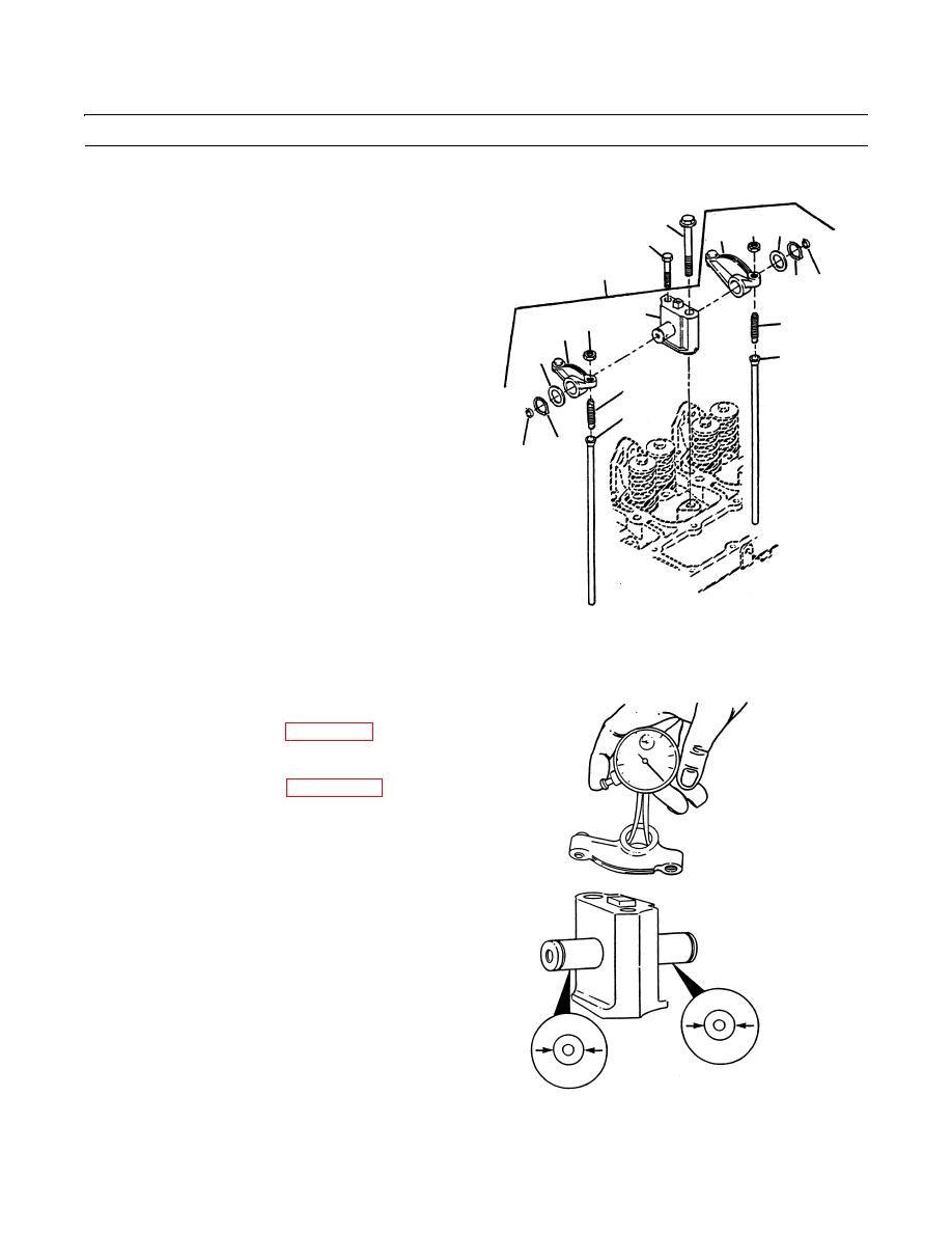
1.
Remove two expansion plugs (7), retaining rings (8)
and washers (9).
NOTE
Do not remove shaft from support. The
support and shaft must be replaced as an
assembly.
409-1007
2.
Remove intake rocker arm (10) and exhaust rocker
arm (11) from support (12).
3.
Remove nuts (1) and adjusting screws (2) from rocker levers (10 and 11).
4.
Repeat steps 1 thru 7 for other five rocker arm assemblies (5).
CLEANING
See Cleaning instructions (WP 0316 00).
INSPECTION
See Inspection instructions (WP 0317 00).
1.
2.
Measure rocker arm bore. Maximum allowable diame-
ter is 0.750 in. (19.05 mm).
3.
Measure rocker arm support shaft diameter. Minimum
allowable diameter is 0.746 in. (18.948 mm).
409-1008
0216 00-2
|
|
Privacy Statement - Press Release - Copyright Information. - Contact Us |
