 |
|||
|
|
|||
|
|
|||
| ||||||||||
|
|
 TM 10-3930-660-24-2
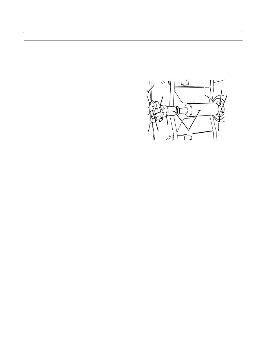
ENGINE ASSEMBLY REPLACEMENT (165 HP) - CONTINUED
0210 00
REMOVAL
NOTE
Note tie wrap locations, then remove and discard all tie wraps that secure electrical wiring, tubing and hoses
to engine.
1.
Remove four screws (1), lockwashers (2), universal
6
joint (3) and driveshaft assembly (4) from input yoke
7
(5) and transmission (6). Discard lockwashers.
8
10
1,2
2.
Remove three screws (7) from engine coupling (8).
3.
Temporarily install two screws (7) removed in step 2
above in two jacking holes (9) of engine coupling (8).
NOTE
If jacking screws only go partly in (less than
3
half way up threads) then jacking screws and
4
9
5
jacking hole threads needs to be cleared of dirt.
409-1787
Follow steps 4-5 to clean threads.
TR01325
4.
Clean threads of jacking screws using wire brush.
5.
Spray solvent cleaning compound on screw thread and
in jacking holes.
6.
Repeat step 5 until jacking screws can be installed
more than halfway up threads of jacking screws.
7.
Tighten two screws (7) evenly until driveshaft assem-
bly (4) and engine coupling (8) separates from engine
dampener (10).
8.
Remove coupling (8) and driveshaft assembly (4)
from vehicle as an assembly.
0210 00-2
|
|
Privacy Statement - Press Release - Copyright Information. - Contact Us |
