 |
|||
|
|
|||
|
|
|||
| ||||||||||
|
|
 TM 10-3930-660-24-2
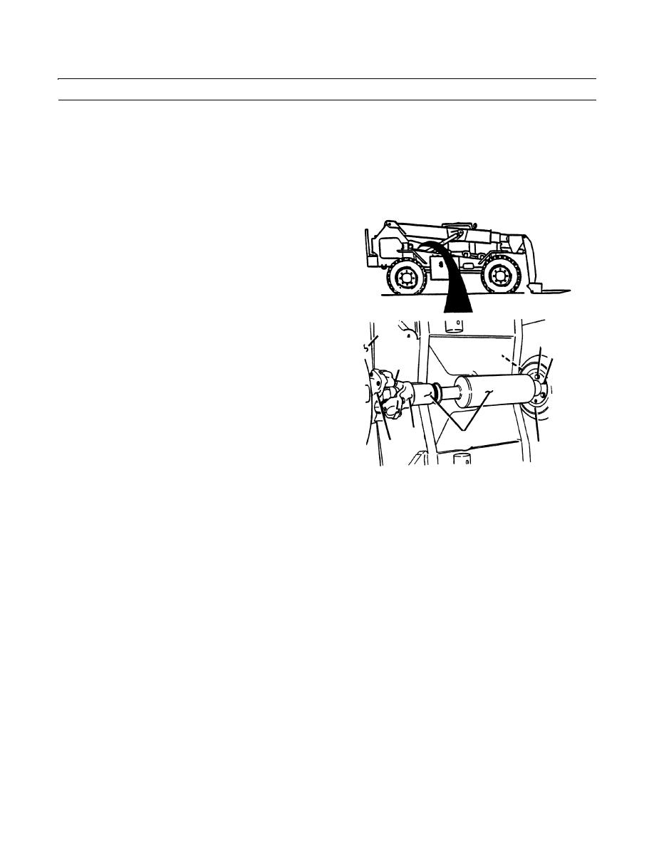
ENGINE ASSEMBLY REPLACEMENT (152 HP) - CONTINUED
0209 00
REMOVAL
NOTE
Note tie down strap locations, then cut and
discard all tie down straps that secure elec-
trical wiring, tubing and hoses to the
engine.
1.
To remove driveshaft assembly (1) from transmission
(2), remove four capscrews (3) and four lockwashers
(4) securing universal joint (5) of driveshaft assembly
to input yoke (6) of transmission. Discard lockwash-
ers.
2.
To remove driveshaft assembly (1) from engine damp-
ener (7), remove three capscrews (8) from engine cou-
pling (9).
2
3.
Temporarily install two of the capscrews (8) into two
8
jacking holes (10) of engine coupling (9).
9
7
3,4
NOTE
If jacking screws only go partly in (less
than half way up threads), then jacking
screws and jacking hole threads needs to
be cleared of dirt. Follow steps 4-5 to
5
1
clean threads.
6
10
4.
Clean threads of jacking screws using wire brush.
409-801
5.
Spray solvent cleaning compound on screw thread and
in jacking holes.
6.
Repeat step 5 until jacking screws can be installed
more than halfway up threads of jacking screws.
7.
Tighten two capscrews (8) evenly until shaft assembly
(1) and engine coupling (9) separate from engine
dampener (7).
8.
Remove coupling (9) and shaft assembly (1) from
vehicle as an assembly.
0209 00-2
|
|
Privacy Statement - Press Release - Copyright Information. - Contact Us |
