 |
|||
|
|
|||
|
|
|||
| ||||||||||
|
|
 TM 10-3930-660-24-1
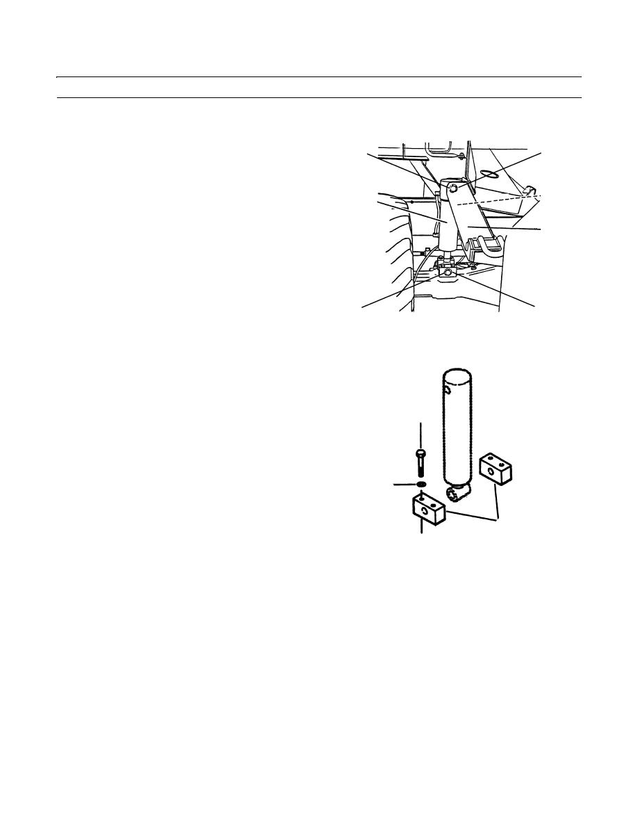
FRAME TILT CYLINDER REPLACEMENT - CONTINUED
0183 00
REMOVAL - CONTINUED
8.
Remove retaining ring (7).
2
3
9.
With assistance, support cylinder and remove rod
pivot pin (8).
10.
Remove frame tilt cylinder (4) from vehicle.
5
4
6
409-4074
8
7
11.
If necessary, remove four capscrews (9), four lock-
washers (10) and two brackets (11) from axle. Discard
9
10
11
409-694
INSTALLATION
1.
If removed, secure two brackets (11) to axle with four new lockwashers (10) and four capscrews (9).
NOTE
Remove caps and plugs as hoses are installed. Wipe all sealing surfaces on cylinder and hoses clean and dry.
2.
Position frame tilt cylinder (4) on vehicle so holes for rod pivot pin line up.
NOTE
Apply anti-seize compound to rod pivot pin as installed.
3.
Install rod pivot pin (8).
4.
Install retaining ring (7) on rod pivot pin (8).
0183 00-3
|
|
Privacy Statement - Press Release - Copyright Information. - Contact Us |
