 |
|||
|
|
|||
|
|
|||
| ||||||||||
|
|
 TM 10-3930-660-24-1
RELIEF VALVE, FRAME TILT/BRAKES REPLACEMENT - CONTINUED
0178 00
REMOVAL
1.
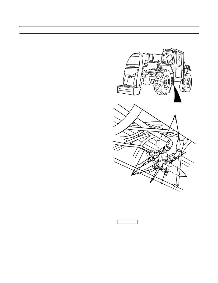
Disconnect five hydraulic hoses (1) from relief valve
(2).
NOTE
Secure valve so it does not fall when mounting
hardware is removed.
2.
Remove two nuts (3), two lockwashers (4) and two
capscrews (5) that secure relief valve (2) to mounting
bracket. Discard lockwashers.
3.
Remove relief valve (2) from vehicle.
INSTALLATION
1
NOTE
Remove cap and plugs as hoses are installed.
Wipe all sealing surfaces on valve and hoses
clean and dry.
1.
Position relief valve (2) so holes on valve flange (6)
line up with mounting bracket holes.
6
NOTE
Apply loctite to threads of all capscrews as
installed.
2.
Place two mounting capscrews (5) through valve
flange (6) and mounting bracket hole.
1
3,4
3.
Install two new lockwashers (4) and nuts (3) on cap-
5
screw (5) and tighten mounting nuts (3) securely.
2
409-671
4.
Connect five hydraulic hoses (1) to relief valve (2) as
tagged and tighten securely.
NOTE
Any time the hydraulic oil has been drained and changed or maintenance has been done on the hydraulic
system, it is possible that the hydraulic pumps have air in the pump cavities. This air must be purged from
the cavity before the pump will operate. If necessary refer to WP 0172 00.
5.
To bleed air from frame tilt and brake hydraulic circuit, start engine (TM 10-3930-660-10).
6.
Operate frame tilt function and tilt vehicle from side to side five times.
7.
Stop engine and relieve hydraulic pressure by operating frame tilt controls (TM 10-3930-660-10).
8.
Repeat steps 5-7 until frame tilt and brake hydraulic circuit is completely bled of air.
9.
Operate equipment, check for leaks and proper operation (TM 10-3930-660-10).
0178 00-2
|
|
Privacy Statement - Press Release - Copyright Information. - Contact Us |