 |
|||
|
|
|||
|
|
|||
| ||||||||||
|
|
 TM 10-3930-660-24-1
STEERING SELECT VALVE MAINTENANCE - CONTINUED
0144 00
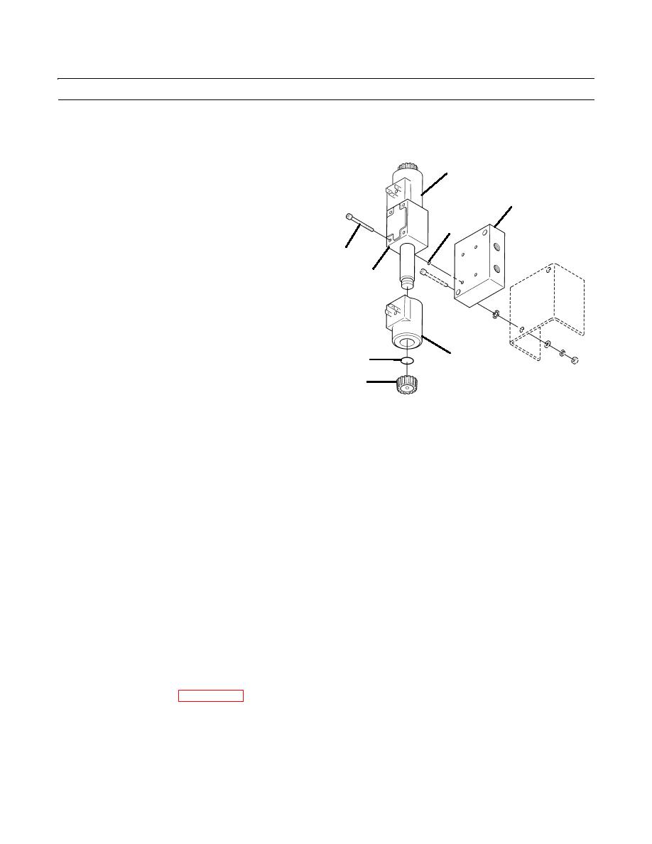
DISASSEMBLY
1.
Remove four capscrews (12) and separate valve body (10) from valve plate (11).
2.
Remove and discard four O-rings (13) from between
14
ports of valve body (10) and valve plate (11).
3.
Separate solenoids (14) from valve body (10).
11
4.
Remove and discard O-ring (16) from between each
solenoid (14) and knob (15).
13
ASSEMBLY
12
1.
Position one new O-ring (16) between each solenoid
10
(14) and knob (15).
14
16
15
409-4040
2.
Secure each solenoid (14) to valve body (10).
3.
Position four new O-rings (13) between ports of valve body (10) and valve plate (11).
4.
Secure valve body (10) to valve plate (11) with four capscrews (12).
INSTALLATION
NOTE
Remove caps and plugs as hoses are installed. Wipe all sealing surfaces on valve and hoses clean and
dry.
Position valve on vehicle as noted during removal.
Note that nuts, lockwashers and washers are accessed from inside the cab tool box. Lockwashers are
located between valve and backside of tool box.
1.
Position valve (3) on vehicle.
2.
Secure with two lockwashers (9), two capscrews (8), two washers (7), two new lockwashers (6) and two nuts (5).
3.
Connect four hydraulic hoses (4) as tagged.
4.
Connect two electrical leads (1) at plugs (2) of steering select valve (3).
5.
Insert plugs (2) of two electrical leads (1) into two socket terminals of steering select valve (3) as tagged.
6.
Connect battery cables (WP 0107 00).
7.
Bleed the steering system hydraulic circuit by selecting four-wheel steering and cycling the steering cylinders five times
(TM 10-3930-660-10).
END OF WORK PACKAGE
0144 00-3
|
|
Privacy Statement - Press Release - Copyright Information. - Contact Us |