 |
|||
|
|
|||
|
|
|||
| ||||||||||
|
|
 TM 10-3930-660-24-1
TURN SIGNAL FLASHER REPLACEMENT - CONTINUED
0084 00
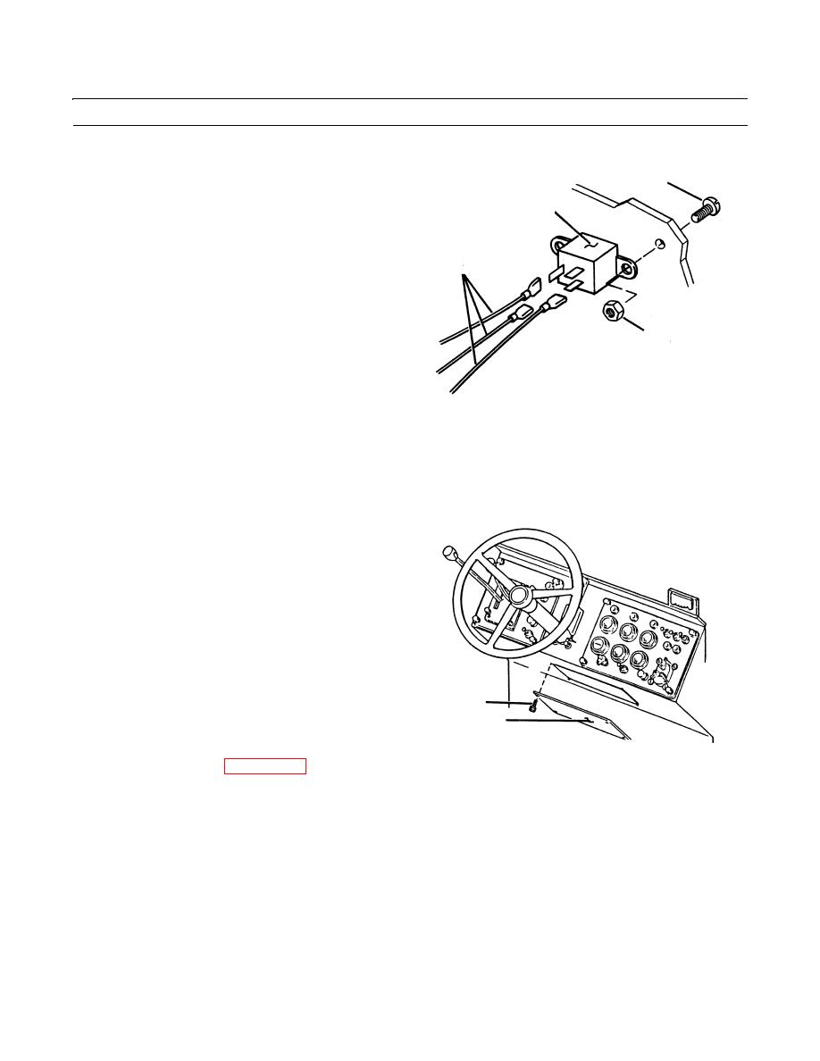
REMOVAL - CONTINUED
2.
Disconnect three electrical leads (3) from flasher (4) at
6
spade connectors.
4
3.
Remove two locknuts (5) and two screws (6) securing
flasher (4) to cab. Remove flasher from cab. Discard
locknuts.
3
5
409-326
INSTALLATION
1.
Position flasher (4) on cab and secure with two screws (6), and two new locknuts (5).
2.
Connect three electrical leads (3) to flasher (4) at spade connectors.
3.
Secure access panel (2) to front console with four cap-
screws (1).
1
2
409-325
4.
Connect battery cables (WP 0107 00).
5.
Turn engine start switch to ON position and check for proper operation of turn signals (TM 10-3930-660-10).
END OF WORK PACKAGE
0084 00-2
|
|
Privacy Statement - Press Release - Copyright Information. - Contact Us |
