 |
|||
|
|
|||
|
|
|||
| ||||||||||
|
|
 TM 10-3930-660-24-1
FORK AUTO LEVELER CIRCUIT BOARD MAINTENANCE - CONTINUED
0079 00
TESTING
1.
Start engine. Raise forks approximately 1 ft (30 cm) off ground. Stop engine (TM 10-3930-660-10).
2.
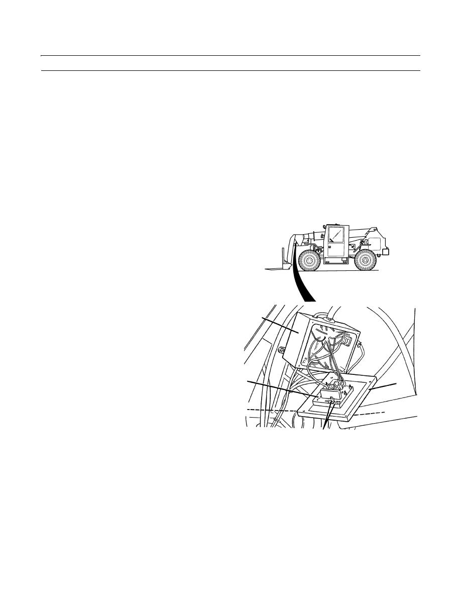
Loosen four screws (1) and separate cover (2) from boom electrical box (3) to provide access to auto leveler circuit
board (4).
CAUTION
Support cover as required so that weight of cover and circuit board is not supported by electrical leads to
board.
NOTE
There are two LED indicators on the auto leveler circuit board. One is labeled "Hi A" and the other is
labeled "Hi B".
3.
Check for proper adjustment of auto leveler switch.
4.
Start engine (TM 10-3930-660-10).
5.
Turn off auto leveler control in cab (TM 10-3930-660-
10).
6.
Place level on forks.
7.
Raise forks to approximately a +6-degree inclination
and observe "Hi A" LED indicator (5).
3
NOTE
The "Hi A" LED indicator should be illu-
minated after forks are raised.
8.
Turn on auto leveler control in cab (TM 10-3930-660-
10) and observe "Hi A" LED indicator (5).
4
2
NOTE
The "Hi A" LED indicator should remain
1
1
illuminated as forks are lowering and go
out when forks are level.
5,6
9.
Turn off auto leveler control in cab and lower forks to
409-4028
approximately a -6-degree inclination. Observe "Hi
B" LED indicator (6).
NOTE
The "Hi B" LED indicator should be illuminated after forks are lowered.
10.
Turn on auto leveler control in cab (TM 10-3930-660-10) and observe "Hi B" LED indicator (7).
NOTE
The "Hi B" LED indicator should remain illuminated as forks are raising and go out when forks are level.
0079 00-2
|
|
Privacy Statement - Press Release - Copyright Information. - Contact Us |