 |
|||
|
|
|||
|
|
|||
| ||||||||||
|
|
 TM 10-3930-660-24-1
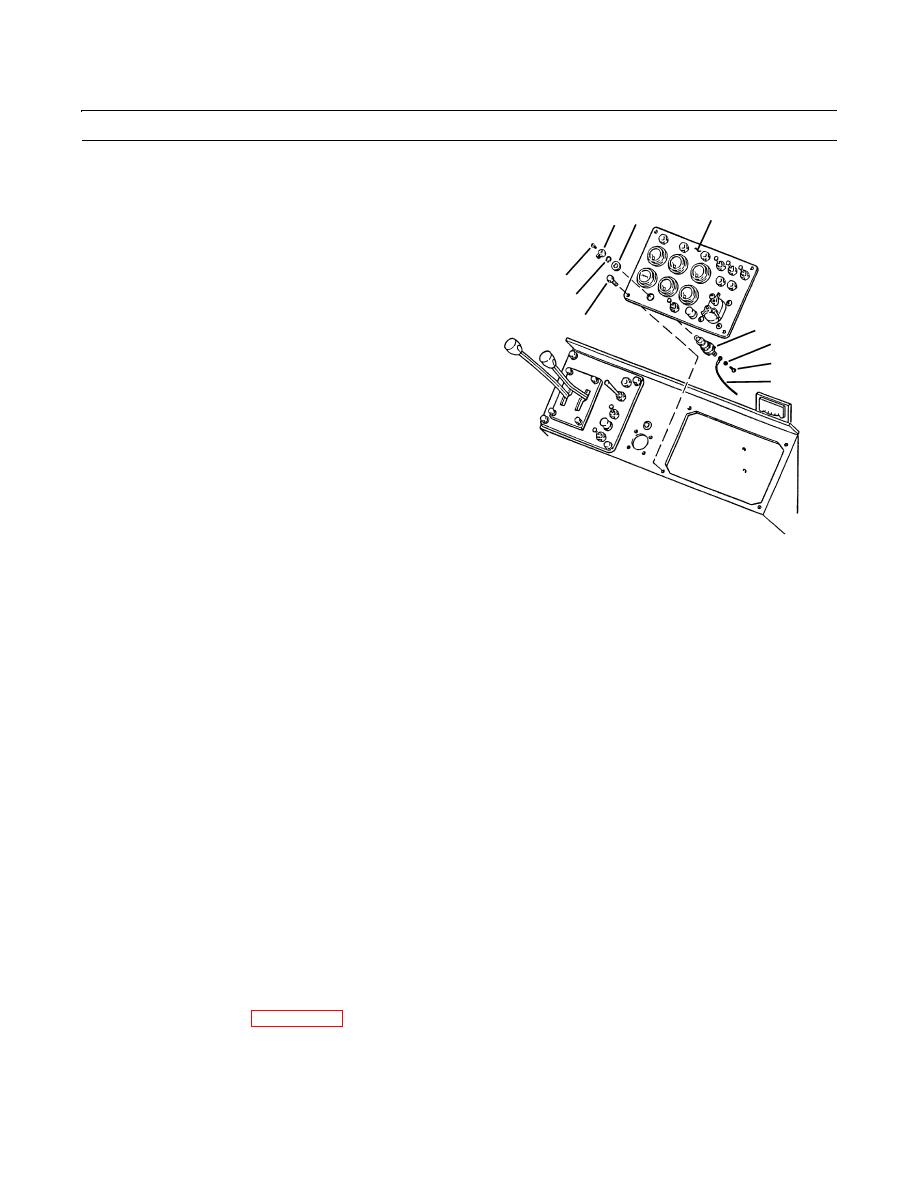
STARTER SWITCH REPLACEMENT - CONTINUED
0072 00
REMOVAL - CONTINUED
2
8 10
3.
Remove five screws (4) and lockwashers (5) securing
electrical leads (6). Remove electrical leads from
switch (3). Discard lockwashers.
4.
Remove starter switch (3) from instrument panel (2).
7
9
NOTE
1
3
5
Note orientation of starter switch and
starter switch knob for use during installa-
4
tion.
6
5.
Remove screw (7) and knob (8) from switch (3).
6.
Remove retaining ring (9) and nut (10) securing
switch (3) to instrument panel (2).
7.
Slide switch (3) out through mounting hole on instru-
ment panel (2).
409-4026
INSTALLATION
NOTE
Position starter switch and starter switch knob as noted during removal.
1.
Slide switch (3) in through mounting hole on instrument panel (2).
2.
Secure switch (3) to instrument panel (1) with nut (10) and retaining ring (9).
3.
Position knob (8) on switch (3) and secure with screw (7).
4.
Connect electrical leads (6) to starter switch (3) as tagged.
5.
Secure electrical leads (6) to switch (3) with five new lockwashers (5) and five screws (4).
6.
Lower and align right-hand instrument panel (2).
NOTE
Apply loctite to threads of capscrews.
7.
Secure right-hand instrument panel (2) with four capscrews (1).
8.
Connect battery cables (WP 0107 00).
END OF WORK PACKAGE
0072 00-2
|
|
Privacy Statement - Press Release - Copyright Information. - Contact Us |
