 |
|||
|
|
|||
|
|
|||
| ||||||||||
|
|
 TM 10-3930-660-24-1
FUEL DRAIN LINES AND MANIFOLD REPLACEMENT (152 HP) - CONTINUED
0036 00
REMOVAL - CONTINUED
NOTE
If necessary, remove engine lifting bracket, water outlet, and thermostat, as an assembly, to provide access to
fuel injector closest to fan side of engine (WP 0055 00).
4.
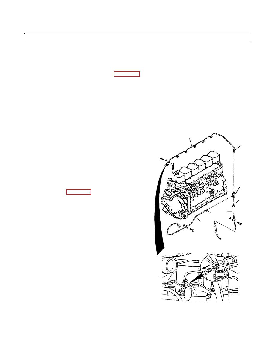
Remove fluid passage bolt (10) and seal (11) from fuel drain manifold (12) at each of the six injectors (13). Discard
seals.
5.
Disconnect fuel drain manifold (12) and fuel drain lines (3 and 6) from tee (14).
NOTE
Seals (15) are an integral part of lines. Inspect seal at end of each line and replace entire line if seal is dam-
aged.
INSTALLATION
12
1.
Connect fuel drain manifold (12) and fuel drain lines
(3 and 6) to tee (14).
15
2.
Install fluid passage bolt (10) and new seal (11) to fuel
drain manifold (12) at each of the six injectors (13).
Torque bolts to 6.5 lb-ft (8.8 Nm).
NOTE
If removed to provide access during
14
removal, install engine lifting bracket,
water outlet, and thermostat, as an assem-
bly, to engine (WP 0055 00).
15
3.
Connect fuel drain line (6) to injection pump (9) with
fluid passage bolt (7) and two new sealing washers
3
(8). Torque bolt to 32 lb-ft (43 Nm).
15
4.
Connect fuel drain line (3) to fuel drain line manifold
6
(6) to engine with two new grommets (5) and two cap-
screws (4). Torque capscrews to 6 lb-ft (8 Nm).
5.
Connect hose (2) to fuel drain line (3) with hose clamp
(1).
11
6.
Start engine and check for leaks (TM 10-3930-660-
10).
13
12
10
409-188
END OF WORK PACKAGE
0036 00-3
|
|
Privacy Statement - Press Release - Copyright Information. - Contact Us |