 |
|||
|
|
|||
|
|
|||
| ||||||||||
|
|
 TM 10-3930-660-24-1
CYLINDER HEAD SERVICE - CONTINUED
0013 00
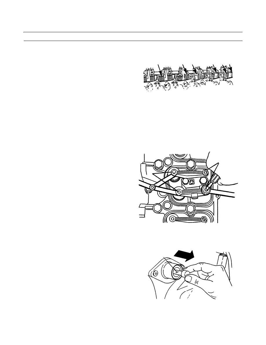
ADJUSTMENT - CONTINUED
3.
Adjust clearances of three intake valves (3) and three
3
4
3
3
4
4
exhaust valves (4).
no. 1
no. 3 no. 2
no. 4
no. 5
no. 6
409-145
NOTE
Intake valve clearance - 0.010 in. (0.254 mm).
Exhaust valve clearance - 0.020 in. (0.508 mm).
Clearance is correct when a slight pull is felt as feeler gauge is slipped between valve stem and rocker
lever.
4.
Loosen adjustment locknut (5). Adjust screw (6) as
required until valve clearance is properly adjusted.
5,6
5.
Tighten adjustment locknut (5) to 6 lb-ft (8 Nm) of
torque. Then recheck valve clearance.
7
409-146
6.
Disengage engine timing pin (2).
2
409-147
0013 00-2
|
|
Privacy Statement - Press Release - Copyright Information. - Contact Us |
